
Method for adjusting a continuous dialysate volume flow in a dialysis machine and dialysis machine

Active Publication Date: 2017-07-04
FRESENIUS MEDICAL CARE DEUTSCHLAND GMBH
View PDF16 Cites 17 Cited by
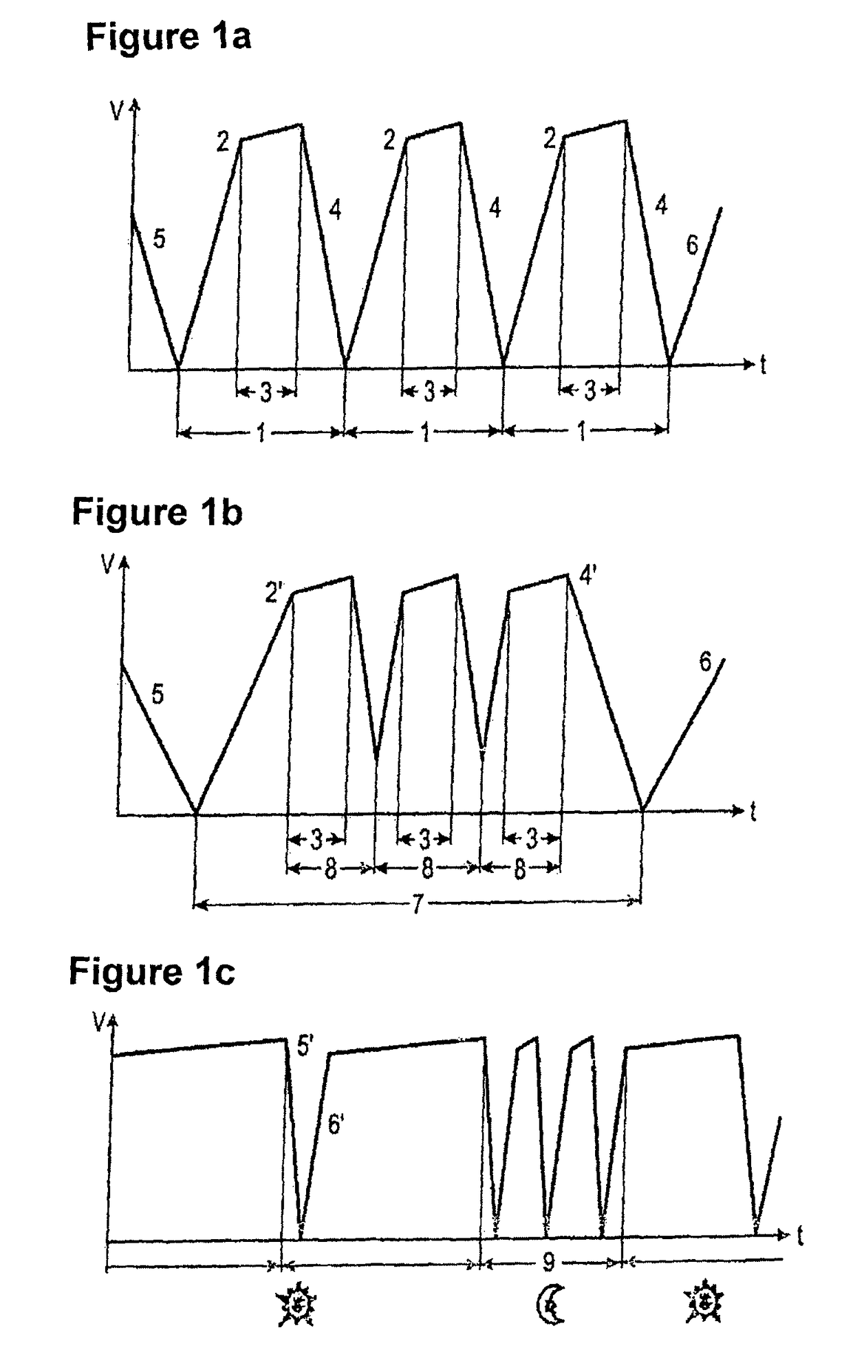
  • Summary
  • Abstract
  • Description
  • Claims
  • Application Information

AI Technical Summary

Benefits of technology

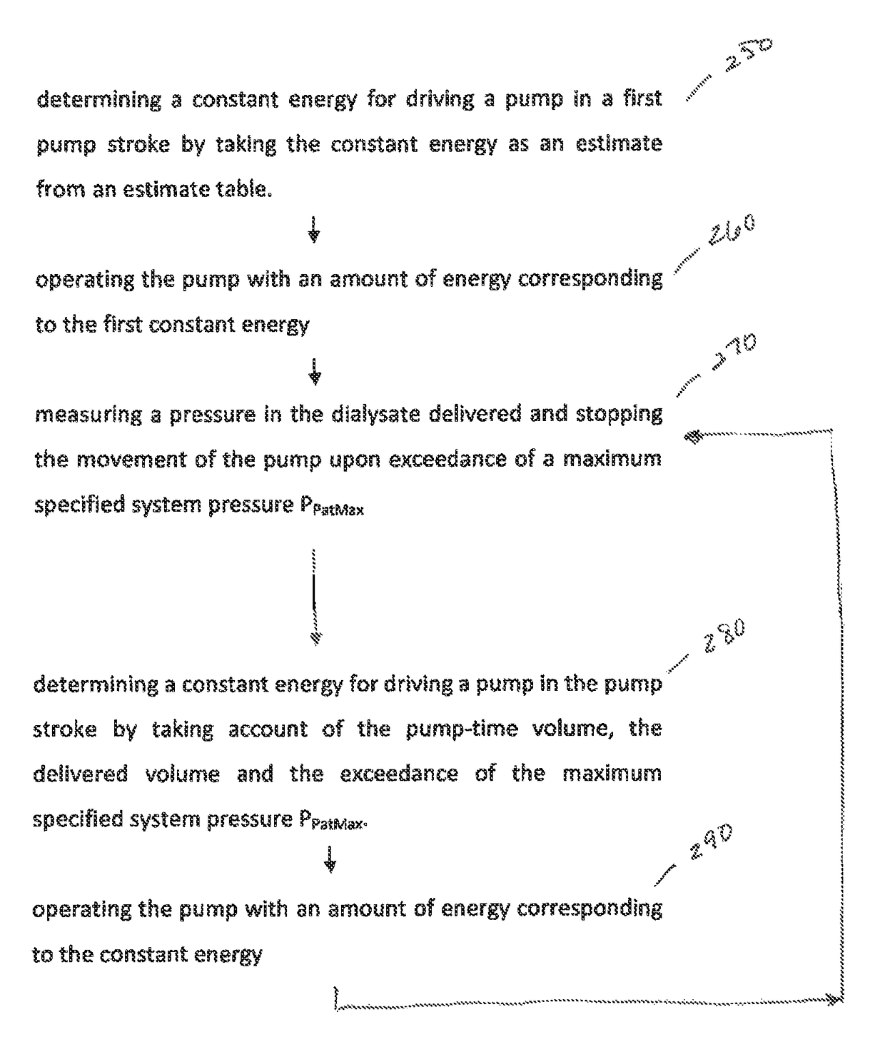
The present invention provides a method for adjusting a continuous dialysate volume flow in a dialysis machine with at least two discontinuous pumps. The method involves adjusting the energy for driving the pumps to be constant with a value determined by the pump-time volume and the desired volume flow. This leads to a change in pressure of the volume flow in the entire system that must be evaluated. However, the energy for the next pump stroke is known, so the change in pressure can be predicted and the pumps operated with the predicted energy. The method allows for easy adjustment of the energy, as well as reaction to changes in the patient feed line or the diaphragm pump characteristic. Additionally, the method simplifies the process of determining the energy characteristic over the entire pump stroke.

Problems solved by technology

Achieving this objective is rendered more difficult by using two discontinuous pumps.
However, this leads to a change in pressure of the entire system, which must be evaluated.
This means that the determination of the patient pressure is characterized by this compensation, which leads to inaccuracies, as the length signal of the length sensor to be taken into account only is comparatively difficult to determine.
This will inevitably cause the exceedance of the previously indicated limit pressure RPatMax.
Finally, the internal tension of the diaphragm is increased very much at the chamber ends and acts against the velocity control, whereby the superposition during start-up or shut-down of the pump systems is rendered more difficult.
What is disadvantageous in the prior art system for adjusting the continuous dialysate volume flow in particular are the high requirements to be satisfied by the control system or the measurement system.
Since these requirements frequently are not satisfied to the desired extent, a non-uniform run of the hydraulic pumps can occur.

Method used


Image

  • Method for adjusting a continuous dialysate volume flow in a dialysis machine and dialysis machine
  • Method for adjusting a continuous dialysate volume flow in a dialysis machine and dialysis machine
  • Method for adjusting a continuous dialysate volume flow in a dialysis machine and dialysis machine

Examples


Embodiment Construction

[0048]Further scope of applicability of the present invention will become apparent from the detailed description given hereinafter. However, it should be understood that the detailed description and specific examples, while indicating preferred embodiments of the invention, are given by way of illustration only, since various changes and modifications within the spirit and scope of the invention will become apparent to those skilled in the art from this detailed description.

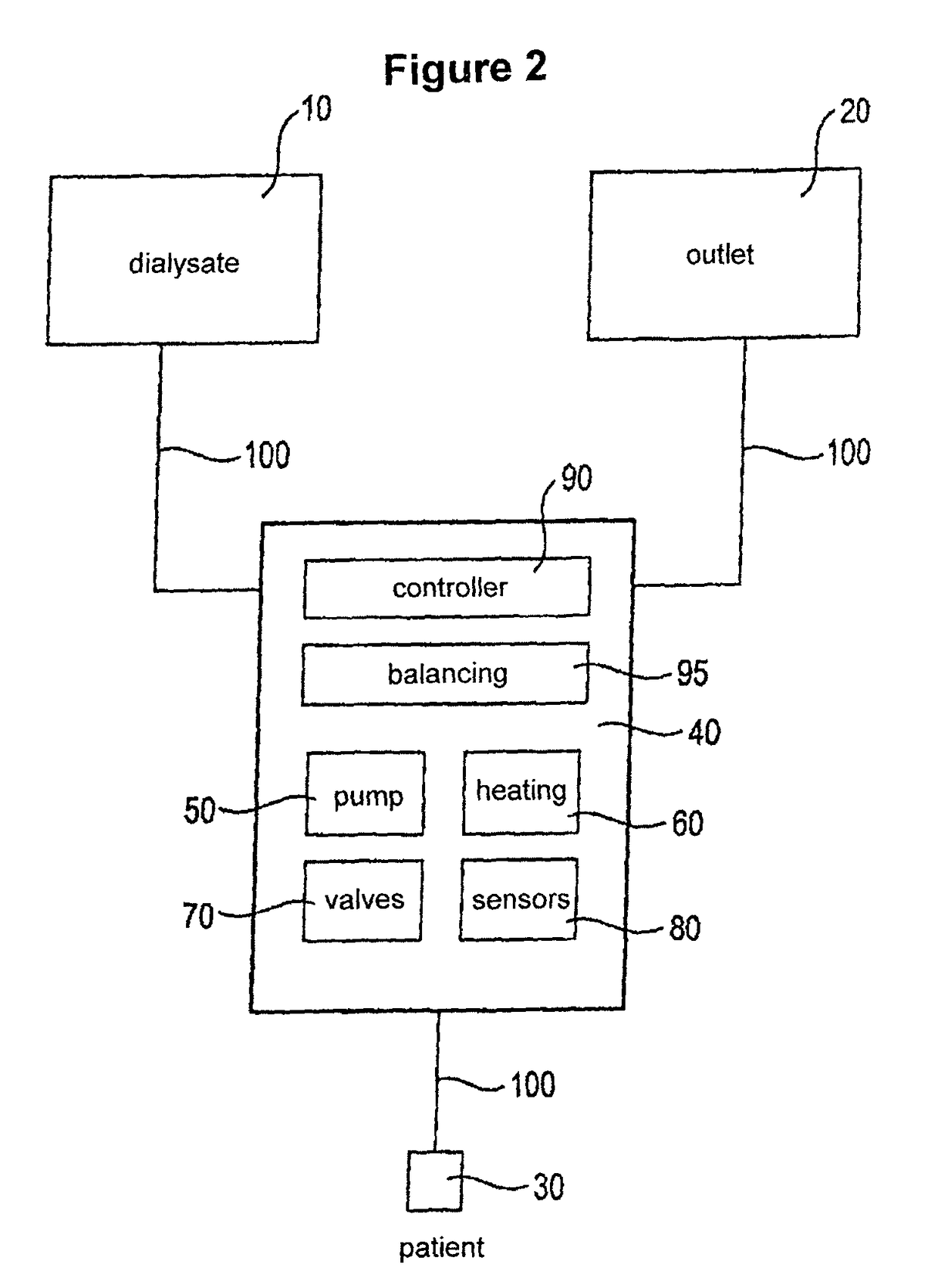
[0049]In the following, the function of a dialysis machine in which the present invention is used should first be described in general. In the exemplary embodiment, the dialysis machine is a peritoneal dialysis machine. In the same or a similar way, the components described below can, however, also be used for a hemodialysis machine.

[0050]The peritoneal dialysis is a variant of artificial hemodialysis in which the abdominal membrane (peritoneum) of the patient well supplied with blood is used as the body's own fi...


PUM


Abstract

A method is provided for adjusting a continuous dialysate volume flow in a dialysis machine with at least two discontinuous pumps and a controller for generating a desired volume flow of the dialysate. The energy for driving the pumps is set to be constant with a value determined corresponding to the pump-time volume of the respective pump stroke and the delivered volume. A dialysis machine for carrying out the aforementioned method is also provided.

Description

[0001]This application claims the benefit of U.S. provisional application No. 61 / 492,952, filed Jun. 3, 2011, and priority of German number 10 2011 103 325.8 filed Jun. 3, 2011, hereby incorporated by reference.BACKGROUND OF THE INVENTION[0002]1. Field of the Invention[0003]2. Description of the Related Art[0004]This invention relates to a method for adjusting a continuous dialysate volume flow in a dialysis machine and a dialysis machine for carrying out the method. The dialysis machine in particular can be a peritoneal dialysis machine.[0005]In the automatic peritoneal dialysis a dialysis machine controls and monitors the introduction of the fresh dialysate into the abdominal cavity and the discharge of the used dialysate. Such dialysis machine, also referred to as cycler, usually fills and drains the abdominal cavity several times during the night, i.e. while the patient sleeps.[0006]A peritoneal dialysis machine according to the prior art is shown in FIG. 14 by way of example. A...

Claims


Application Information

Patent Timeline
IPC IPC(8): A61M1/28A61M1/16
CPCA61M1/28A61M1/1601A61M2205/3379A61M2206/22A61M1/166A61M1/282A61M1/155A61M1/1522A61M1/154A61M1/159A61M1/1524A61M1/153A61M1/1565A61M1/1561
Inventor HEDMANN, FRANKGRIESSMANN, ERIKWICH-HEITER, JOACHIMSEBESTA, SVEN
Owner FRESENIUS MEDICAL CARE DEUTSCHLAND GMBH
Learn More