Method and magnetic resonance system for automated determination of an acquisition volume related to an examination region for the acquisition of a magnetic resonance data set

a magnetic resonance and automated determination technology, applied in the direction of magnetic measurement, instruments, nmr measurement, etc., can solve the problems of essentially only cuboid volume being excited, no longer delivering any contribution, and almost no contribution from tissue outside the acquisition volum

Active Publication Date: 2017-06-27
SIEMENS HEALTHCARE GMBH
View PDF14 Cites 3 Cited by
  • Summary
  • Abstract
  • Description
  • Claims
  • Application Information

AI Technical Summary

Benefits of technology

[0014]An object of the present invention is to provide a method and a magnetic resonance system with which the acquisition volume can be established automatically.
[0019]In order to describe or establish the envelope, it is sufficient to specify node points. Alternatively, the envelope can be established by an arbitrary number of discrete points. The calculation of the envelope significantly facilitates the subsequent calculation of the rectangle, since the cross section of the examination region typically includes a number of image elements, of which most are irrelevant in the determination of the surrounding rectangle.
[0032]The “rotating calipers” algorithm can be used to further reduce the calculation time.
[0033]Given a rotation with a small rotation angle, the area of a rectangle normally changes only significantly. In order to simplify the number of side surfaces of the acquisition volume, given use of a plurality of rectangles the rotation angles of the rectangles can therefore be standardized. The area of most of the rectangles that (as before) encloses the respective organ cross section is then no longer minimal, but the adjacent side surfaces can be interpolated more easily.
[0034]In an embodiment, a polygon can be generated based on the minimized or minimal rectangle in that projecting vertices of the rectangle can be considered as being “shortened” by connection lines. However, each of these connection lines increases the number of vertices of the polygon, which is why more saturation bands are also consequently required in order to generate an acquisition volume with such an outer surface. The number of overlapping regions of the saturation bands also increases with the increasing number of saturation bands, which entails corrections in the calculation of the flip angle of the saturation pulses, the gradient strengths and the temporal and spatial order of the saturation bands. In particular, the saturation effect in the first saturated bands decreases increasingly with a rising number of saturation bands since the magnetization in these regions is partially relaxed again up to the radiation of the excitation pulse of the actual spectroscopic or imaging experiment. The acquisition volume is therefore better adapted to the examination region, whereby partial volume effects are reduced.

Problems solved by technology

In contrast to this, in spectroscopic experiments without volume selection the problem exists that a superposition of desired and unwanted signals always results upon acquisition of signals from all regions of the examination subject within the field of view or radiation pattern of the coil; for example, signal intensities from different body regions superimpose in the spectrum generated from the raw data.
Due to the pre-saturation, the tissue outside of the acquisition volume no longer delivers any contribution, or delivers almost no contribution.
However, it is disadvantageous that essentially only cuboid volumes can be excited.
In this method, a complete automation is still not achieved because the acquisition volume or, respectively, the examination subject using which the saturation bands are placed is to be segmented manually.

Method used


Image

  • Method and magnetic resonance system for automated determination of an acquisition volume related to an examination region for the acquisition of a magnetic resonance data set
  • Method and magnetic resonance system for automated determination of an acquisition volume related to an examination region for the acquisition of a magnetic resonance data set
  • Method and magnetic resonance system for automated determination of an acquisition volume related to an examination region for the acquisition of a magnetic resonance data set

Examples


Embodiment Construction

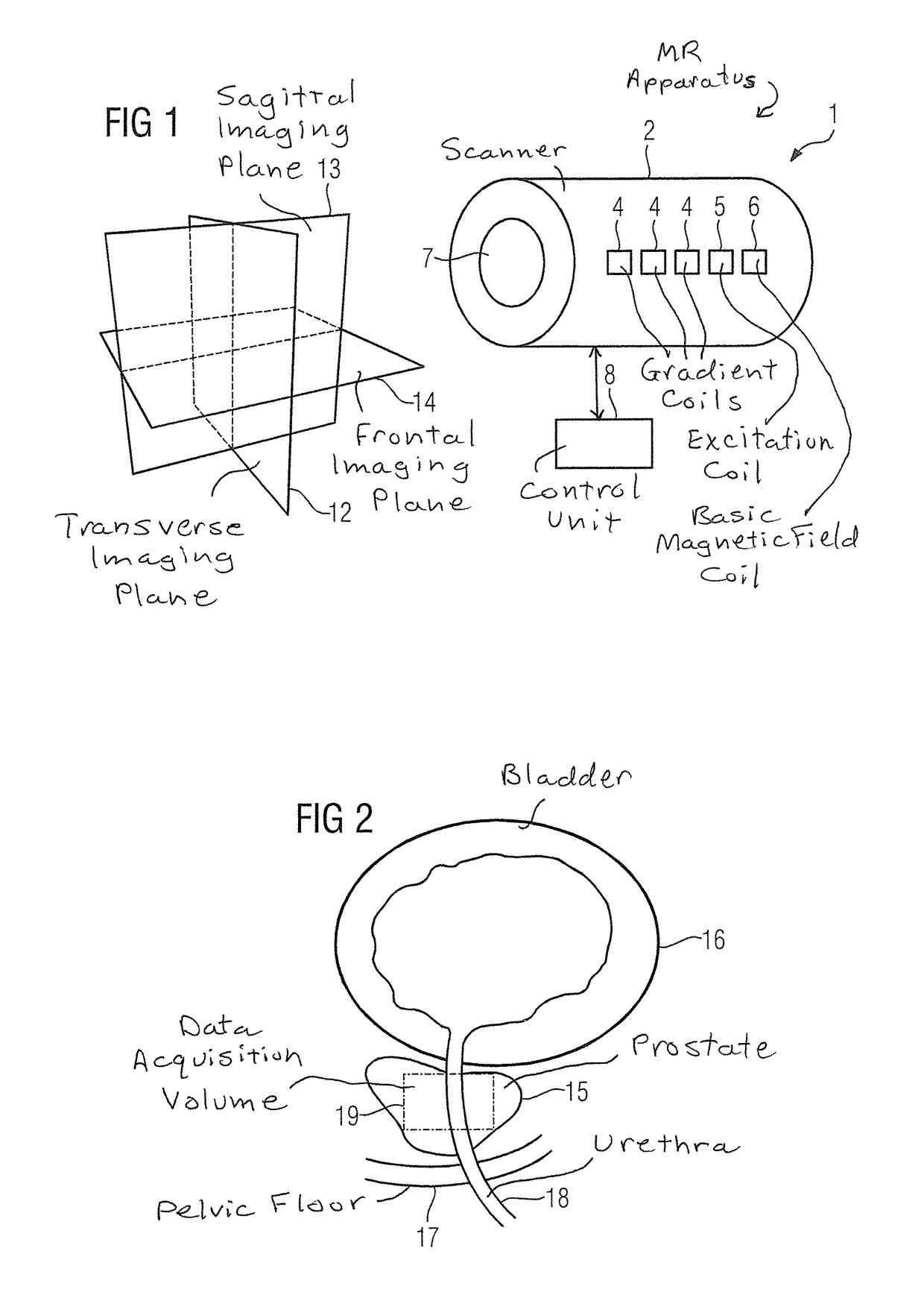
[0050]FIG. 1 shows a magnetic resonance apparatus 1 that has a magnet unit (scanner) 2 as well as a control unit 8. Although the magnet unit 2 is designated generally, it is composed of a number of components. For example, it includes three gradient coils 4, an excitation coil 5 to generate RF pulses, and a coil 6 to generate the basic magnetic field B0.

[0051]A patient who is moved into the magnet 2 via the opening 7 can be positioned with positioning aids so that the examination region—typically the head or a defined organ, for example the liver, the kidneys or the prostate—lies in the homogenous region of the basic magnetic field B0.

[0052]For better orientation, a convention exists for naming primary slice planes that are in particular used in the acquisition of first overview images. The transverse plane 12 lies orthogonally to the longitudinal axis of the patient and divides said patient into an upper part and lower part. The sagittal plane 13 transects the patient in the middle...


PUM


Abstract

In a computerized method and apparatus to automatically determine an acquisition volume of an examination region for the acquisition of a magnetic resonance data set, at least one magnetic resonance image data set is acquired that at least partially images an examination region, and the magnetic resonance image data set is processed into at least one magnetic resonance image. The examination region is segmented and at least one envelope enclosing a segment is determined. At least one rectangle including the envelope is determined. The acquisition volume is calculated using the rectangle.

Description

BACKGROUND OF THE INVENTION[0001]Field of the Invention[0002]The present invention concerns a method and magnetic resonance system for automated determination of an acquisition related to an examination region for acquisition of a magnetic resonance data set.[0003]Description of the Prior Art[0004]To acquire magnetic resonance data sets, energy is always injected (radiated) into a three-dimensional volume with a transmission coil. The volume can be significantly smaller in one direction (the direction of what is known as the slice gradient) than in the two other spatial directions. Such a situation is referred to as the excitation of a slice—this is primarily the case in two-dimensional imaging, as well as in spectroscopic imaging. In contrast to this, the term “excitation volume” is prevalent in three-dimensional imaging and spectroscopic experiments. As used herein, the designation “acquisition volume” means the volume excited by energy injection within the scope of the acquisitio...

Claims


Application Information

Patent Timeline
Patent Type & Authority Patents(United States)
IPC IPC(8): G01R33/48G01R33/483G01R33/54G01R33/56
CPCG01R33/483G01R33/4838G01R33/543G01R33/5608
Inventor NEJI, RADHOUENEREQUARDT, MARTIN
Owner SIEMENS HEALTHCARE GMBH
Why Eureka
Try Eureka