
Configurable counterweight device and system for a material handling machine

a counterweight device and material handling technology, applied in the direction of lifting devices, cranes, constructions, etc., can solve the problems of ineffective design, no prior art considers the value of counterweight devices as crosses, and the difficulty of creating universal cross-over accessories to improve cross-over functions, etc., to achieve the effect of maximizing the cross-over functionality of existing equipment, improving the center of gravity control of said vehicles, and reducing labor costs

Active Publication Date: 2017-06-27
RODEN THOMAS V +1
View PDF6 Cites 1 Cited by
  • Summary
  • Abstract
  • Description
  • Claims
  • Application Information

AI Technical Summary

Benefits of technology

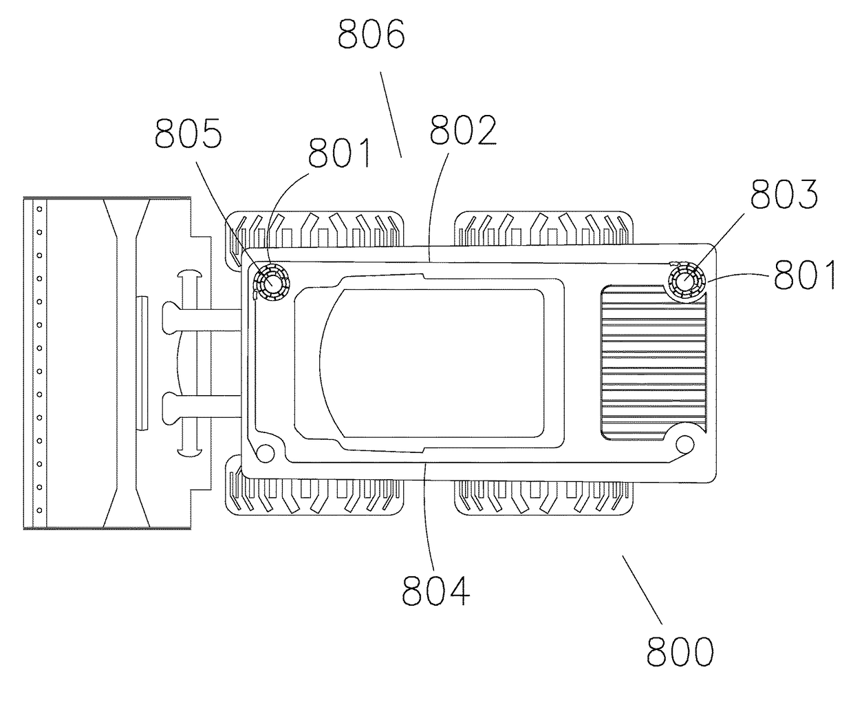
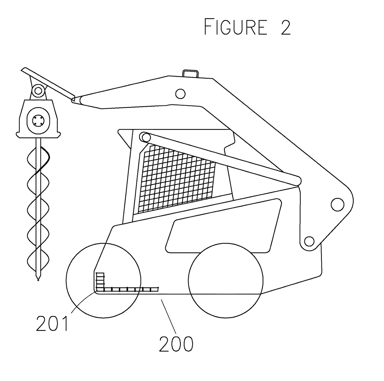
[0013]According to the intention of the invention herein, a single counterweight device and system may be attached around one or more sides of a vehicle along one or more planar paths and in parallel or intersecting direction. Its thin linear (space saving) design enables the device to be attached to the bottom of a material handling vehicle, improving center of gravity control of said vehicle. Alternatively, multiple devices and systems may be strategically positioned in choice configurations, moving together or separately along one or more planar surfaces, at parallel or intersecting direction on a machine to achieve a desired type of counterweighing effect. The ability to transfer weights between front, back and proximal sides independently or in coordination with each other on a vehicle may be critically important to multi-terrain vehicles that often travel along sloped or uneven surfaces and are subject to imbalance between its proximal sides. Said device and system may be scaled down in size for the ability to finely adjust counterweight load or alternatively scaled up in size to cross fit smaller vehicles to meet heavier work demands. The device and system of this invention is versatile and adaptable to a diverse variety of machinery designs. The ability to specially tailor configuration of a system specific to a desired functionality for a machine is incredibly valuable in the industry, allowing users to maximize cross over functionality of their existing equipment.A. Elements of Invention
[0016]The counterweight matter of this invention may be solid, semi-solid or fluid (i.e. liquid, pliable or flowable solid matter) but essentially may be moved along one or more substantially planar paths, in dividable units, said counterweight units transferable over straight, curved or angled portions or surfaces along said planar path without substantially obstructing its own movement to enable compaction or consolidation of said weights in organized fashion, such as rolling or folding of solid weights, etc. Flowable, pliable or liquid weights may be more easily transferred through tube or pipe system, contained or compacted within valve-chambers. Said valve-chambered pipe system functioning as both planar path of movement and transfer element and may take on straight, curved or angled shapes. The additional ease of moving fluid matter in free floating manner allows counterweights of this invention to travel through multiple planar paths concurrently by at least a single drive and control mechanism.
[0022]Total amount of weight per surface area unit may further be maximized by this invention by layering method. At a minimum, a first layer of adjacently positioned individual counterweights as described above is provided. A secondary lateral layer(s) of individual counterweights may be attached onto said first or prior layer of counterweights to increase counterweight load per surface area unit. The individual counterweights of the secondary lateral layer(s) should also be positioned in adjacent free manner to minimize interference of movement over curved or angled surfaces. The freedom to pivot and move over uneven surfaces also provide ability to roll together in multiple layers over a rotary axle end or in a folded pattern. Additional secondary lateral layers may be attached in similar manner to increase and maximize total counterweight load per available surface area on a machine. Counterweights may be spaced apart at variable distances on said transfer element to facilitate unique manner of locating and varying the weights on a machine of a given shape and design. Spacing between weights may also allow multiple layers to roll together more effectively. For example, greater space in between individual counterweights in the upper layers will minimize obstruction of weights within and between the layers when they are cumulatively rolled together.E. Drive Device & Energy Source

Problems solved by technology

As such, it is difficult to create universal cross over accessories to improve cross over functions for material handling machines given the great disparity in machine design and construction.
Yet, none of the prior art considers the value of counterweighing devices as a cross-over tool.
Existing counterweighing devices are fairly rudimentary in nature and ineffective in design.
The motor being necessarily attached to the force arm renders this design awkward and space consuming.
This device is impractical for most material handling machines that lack available space to start.
To date, existing devices are ineffective in providing maximal benefit to counterweighing systems.
Furthermore, where a definition or use of a term in a reference, which is incorporated by reference herein, is inconsistent or contrary to the definition of that term provided herein, the definition of that term provided herein applies and the definition of that term in the reference does not apply.

Method used


Image

  • Configurable counterweight device and system for a material handling machine
  • Configurable counterweight device and system for a material handling machine
  • Configurable counterweight device and system for a material handling machine

Examples


Embodiment Construction

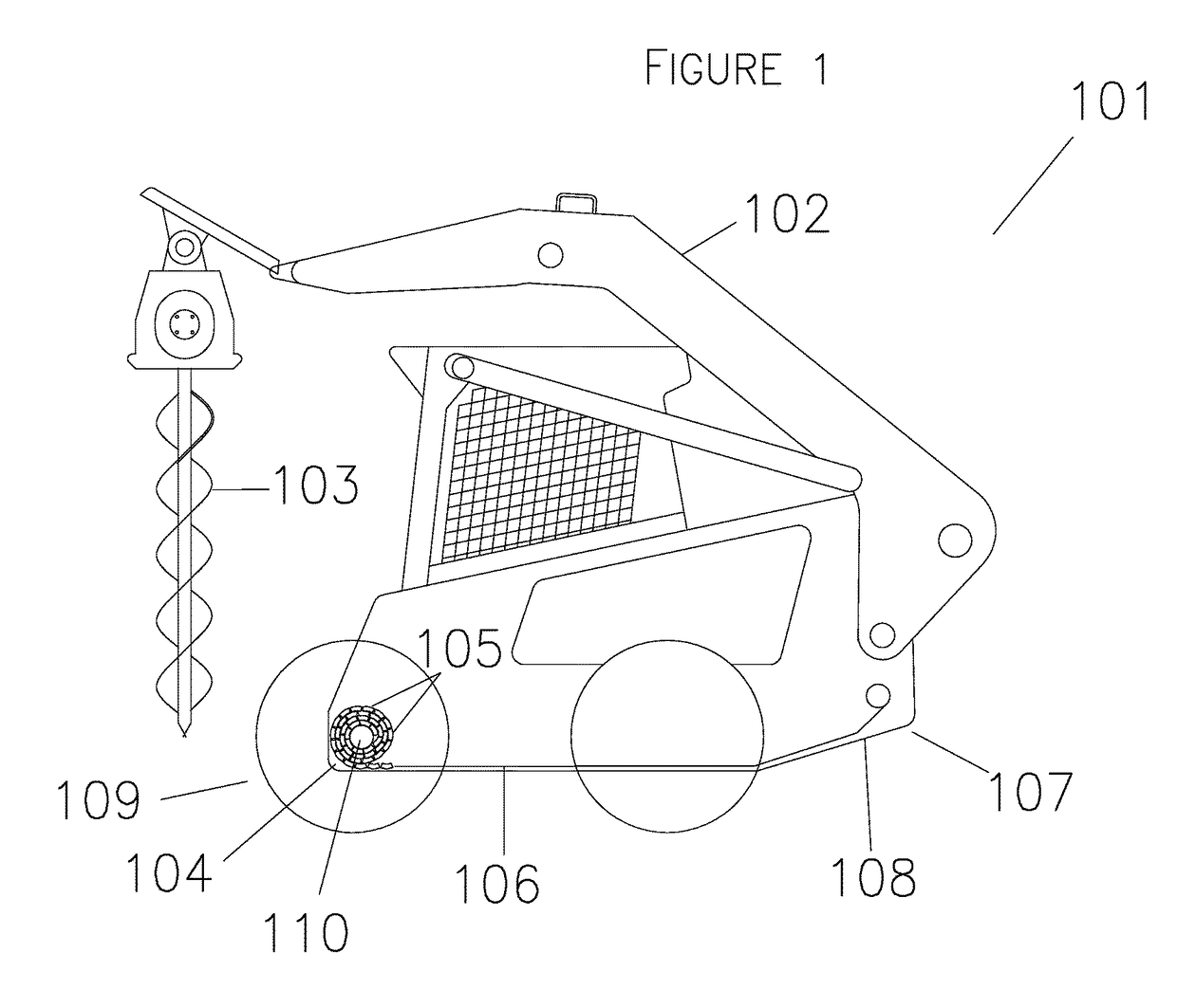
[0038]Reference will now be made in detail to exemplary aspects of the present invention which are illustrated in the accompanying drawings. Wherever possible, the same reference numbers will be used throughout the drawings to refer to the same or like parts.

[0039]Referring to FIG. 1, a vehicle type material handling machine 101 having a work arm (boom) 102 carrying a drill frontward 103. A counterweight device 104 of this invention, containing a plurality of individual solid form counterweights 105 along a linear planar path 106 attached to the bottom 107 of the vehicle. In this case, the counterweight device 104 is held within the chassis 108 of the vehicle, protected from external debris. It is further possible to achieve an even lower center of gravity on hydrostatic vehicles that do not rely on a chassis configuration. In such case, the linear planar device 104 may be attached at lower level external to vehicle's bottom surface 107 with still sufficient clearance to avoid inter...


PUM


Abstract

The present invention provides a configurable and variable counterweight system for a material handling machine comprising one or more planar paths, said planar paths containing any one or combinations of straight, curved or angled portions between at least a first and second end, said planar path having transferable counterweights, said planar path or counterweights communicating with a control device and system, said control device and system comprising one or more drive unit and optionally one or more sensors, said counterweights being able to move along any curved, angled or straight portions of said planar path.

Description

CROSS REFERENCE TO RELATED APPLICATIONS[0001]This continuation-in-part utility patent application claims priority benefit of and incorporates by reference the full and complete disclosure of pending patent application Ser. No. 13 / 199,356, filed Aug. 27, 2011.FEDERALLY SPONSORED RESEARCH OR DEVELOPMENT[0002]Not applicable.REFERENCE TO SEQUENCE LISTING, A TABLE, OR A COMPUTER LISTING APPENDIX[0003]Not applicable.COPYRIGHT NOTICE[0004]A portion of the disclosure of this patent document contains material that is subject to copyright protection. The copyright owner has no objection to the facsimile reproduction by anyone of the patent document or patent disclosure as it appears in the Patent and Trademark office, patent file or records, but otherwise reserves all copyright rights whatsoever.BACKGROUND[0005]Field of Invention[0006]The present invention relates to a configurable counterweight device and system attachable to material handling machines.[0007]Background of the Invention[0008]...

Claims


Application Information

Patent Timeline
Patent Type & Authority Patents(United States)
IPC IPC(8): E02F9/18B66F9/075E02F3/96B66C23/72
CPCE02F9/18B66C23/72B66F9/07554E02F3/96
Inventor RODEN, THOMAS VWERNER, EDWARD S
Owner RODEN THOMAS V
Learn More