
Stationary obstacle identification system

a technology of obstacle identification and station, applied in the direction of automatic aircraft landing aids, aircraft traffic control, aircraft ground control, etc., can solve the problems of pilots not being able to detect obstacles located in blind spots, pilots not being able to monitor and difficulty in monitoring aircraft extremes during ground operations. , to achieve the effect of limiting the transmission distance of transmitted signals and reducing clutter

Active Publication Date: 2017-06-20
HONEYWELL IFL PATENT SERVICES
View PDF11 Cites 1 Cited by
  • Summary
  • Abstract
  • Description
  • Claims
  • Application Information

AI Technical Summary

Problems solved by technology

Stationary obstacles on the ground, such as buildings, fences, tethered obstacles, and various temporary obstacles, may lie in the path of the aircraft.
However, in many instances, due to the dimensions of the aircraft (e.g., large wing sweep angles, distance from cockpit to wingtip) and the pilot's limited field of view, it can be difficult to monitor extremes of the aircraft during ground operations.
As a result, the pilot may fail to detect obstacles that are located in “blind spots” in proximity to the aircraft.
In many cases, the pilot may not detect an obstacle until it is too late to take corrective action.
Collisions with a stationary obstacle can not only damage the aircraft, but can also put the aircraft out of service and result in flight cancellations.
The costs associated with the repair and grounding of an aircraft can be significant.

Method used


Image

  • Stationary obstacle identification system
  • Stationary obstacle identification system
  • Stationary obstacle identification system

Examples


Embodiment Construction

[0014]The following detailed description is merely exemplary in nature and is not intended to limit the invention or the application and uses of the invention. As used herein, the word “exemplary” means “serving as an example, instance, or illustration.” Thus, any embodiment described herein as “exemplary” is not necessarily to be construed as preferred or advantageous over other embodiments. All of the embodiments described herein are exemplary embodiments provided to enable persons skilled in the art to make or use the invention and not to limit the scope of the invention which is defined by the claims. Furthermore, there is no intention to be bound by any expressed or implied theory presented in the preceding technical field, background, brief summary, or the following detailed description.

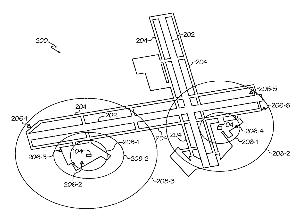
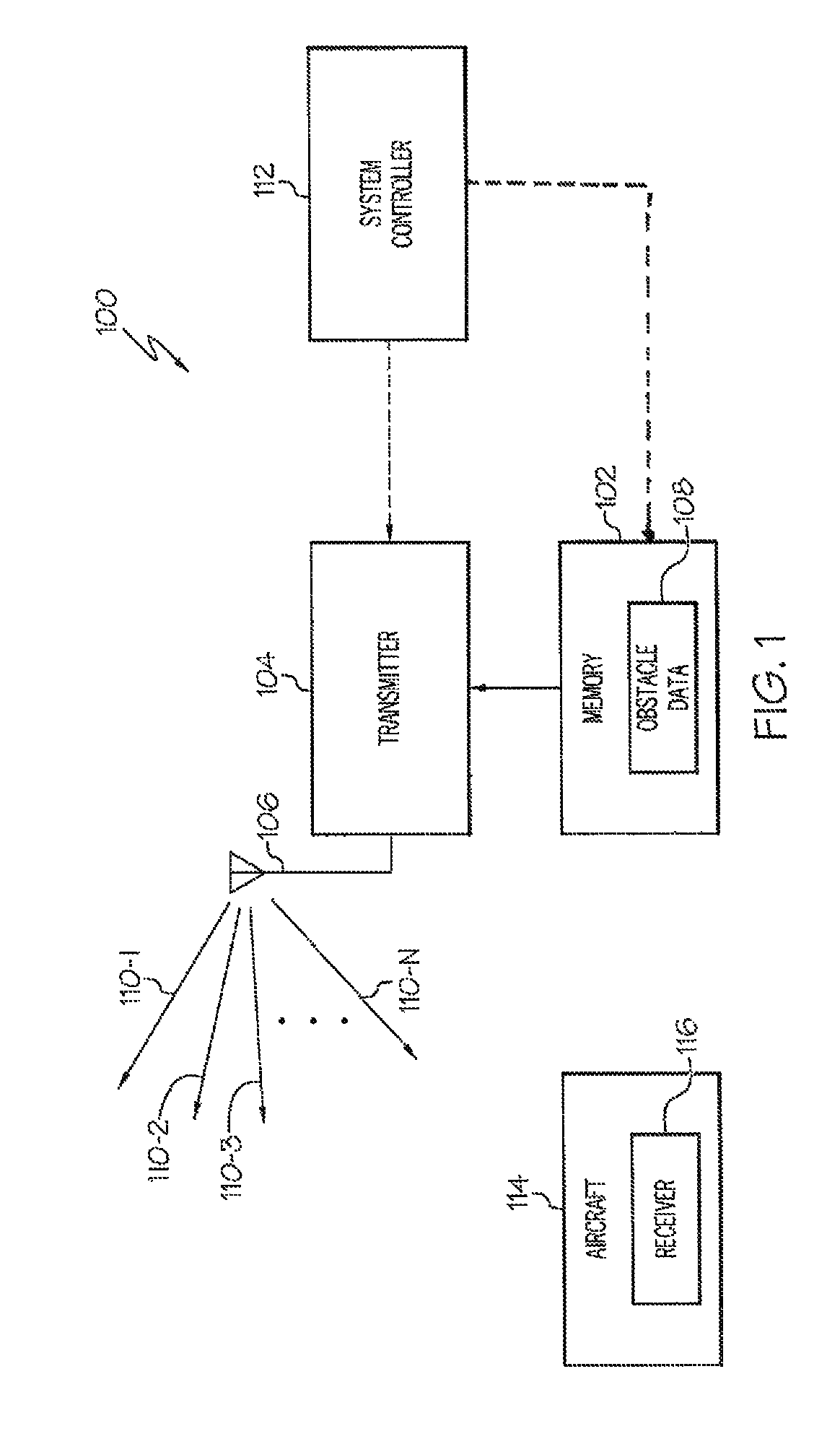
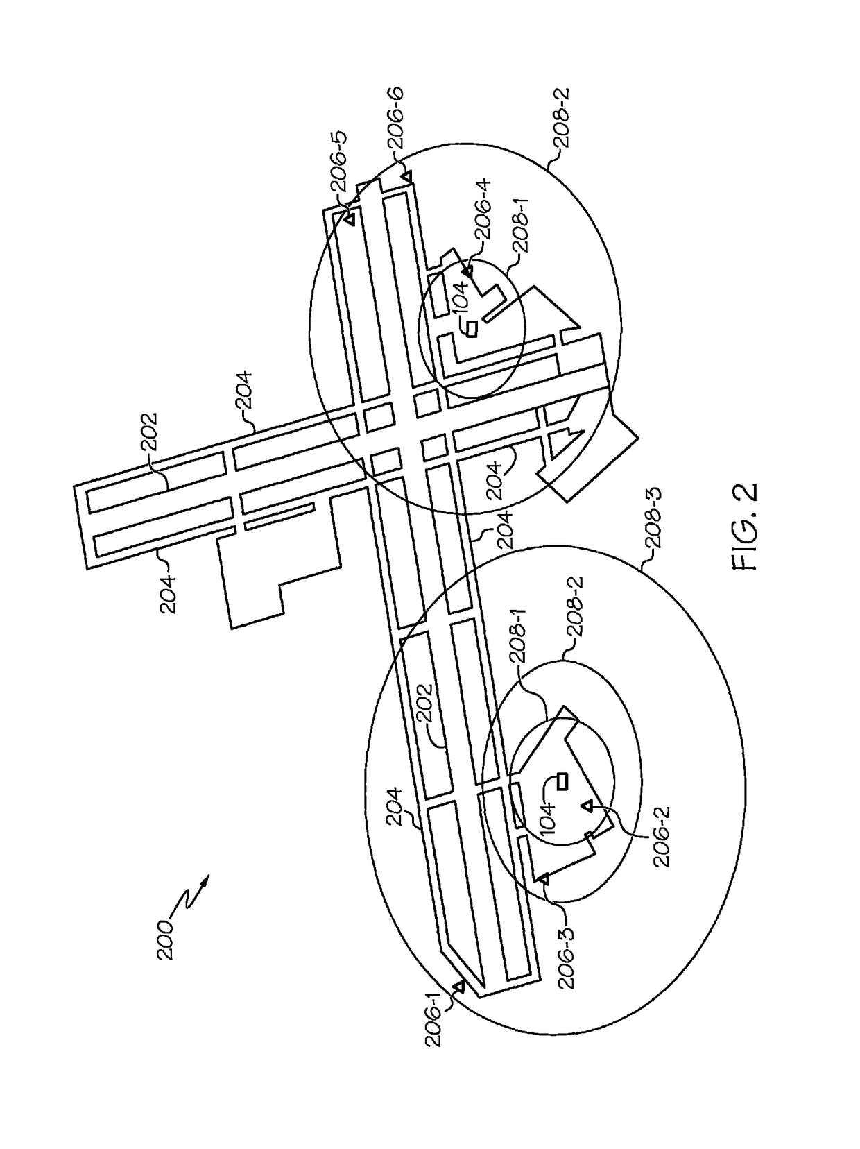
[0015]Referring first to FIG. 1, a functional block diagram of one embodiment of a stationary object identification system is depicted and includes a memory 102, a transmitter 104, and a broadc...


PUM


Abstract

A stationary object identification system includes memory and a transmitter. The memory has obstacle data stored therein that includes a plurality of parameters associated with each of a plurality of stationary obstacles located at a location, such as an aerodrome. The transmitter is in operable communication with the memory and is configured to generate a plurality of signals. Each of the signals is associated with a different one of the stationary obstacles and has a power level representative of the plurality of parameters associated with the stationary obstacle.

Description

TECHNICAL FIELD[0001]The present invention generally relates to stationary obstacle avoidance, and more particularly relates to a stationary obstacle identification system.BACKGROUND[0002]Aircraft pilots often maneuver an aircraft while on the ground. This may happen during ground operations such as when the aircraft is taxiing, being maneuvered to or from a hangar, or to or from a terminal.[0003]Stationary obstacles on the ground, such as buildings, fences, tethered obstacles, and various temporary obstacles, may lie in the path of the aircraft. These obstacles can be detected by the pilot via line of sight. However, in many instances, due to the dimensions of the aircraft (e.g., large wing sweep angles, distance from cockpit to wingtip) and the pilot's limited field of view, it can be difficult to monitor extremes of the aircraft during ground operations. As a result, the pilot may fail to detect obstacles that are located in “blind spots” in proximity to the aircraft. In many cas...

Claims


Application Information

Patent Timeline
Patent Type & Authority Patents(United States)
IPC IPC(8): G08G5/00G08G5/02G08G5/06
CPCG08G5/025G08G5/065G08G5/04G08G5/0013G08G5/0026
Inventor KURGAN, YURIYCONNER, KEVIN J.
Owner HONEYWELL IFL PATENT SERVICES
Learn More