De-coupling capacitance placement

a capacitance placement and capacitance technology, applied in the field of decoupling capacitance placement, can solve the problems of reducing the effective voltage seen by the integrated circuit element, affecting circuit performance, and large switching current flow in the power and ground network, so as to improve the effect of decoupling performan

Inactive Publication Date: 2017-06-20
INT BUSINESS MASCH CORP
View PDF9 Cites 1 Cited by
  • Summary
  • Abstract
  • Description
  • Claims
  • Application Information

AI Technical Summary

Benefits of technology

This patent is about a method and system for placing decoupling capacitors in an integrated circuit. The method involves receiving information about the placement of circuit blocks and calculating the optimal placement for decoupling capacitors based on this information. The decoupling capacitors are then placed in a specific pattern to improve performance. The system can also move circuit elements or decoupling capacitors to avoid collisions and route the integrated circuit. Overall, this method and system allow for more efficient placement of decoupling capacitors and improved performance of the integrated circuit.

Problems solved by technology

Shrinking device dimensions, faster switching frequencies, and increasing power consumption in deep sub-micrometer technologies cause large switching currents to flow in the power and ground networks.
IR-drop reduces the effective voltage seen by integrated circuit elements and may negatively affect circuit performance.

Method used


Image

  • De-coupling capacitance placement
  • De-coupling capacitance placement
  • De-coupling capacitance placement

Examples


Embodiment Construction

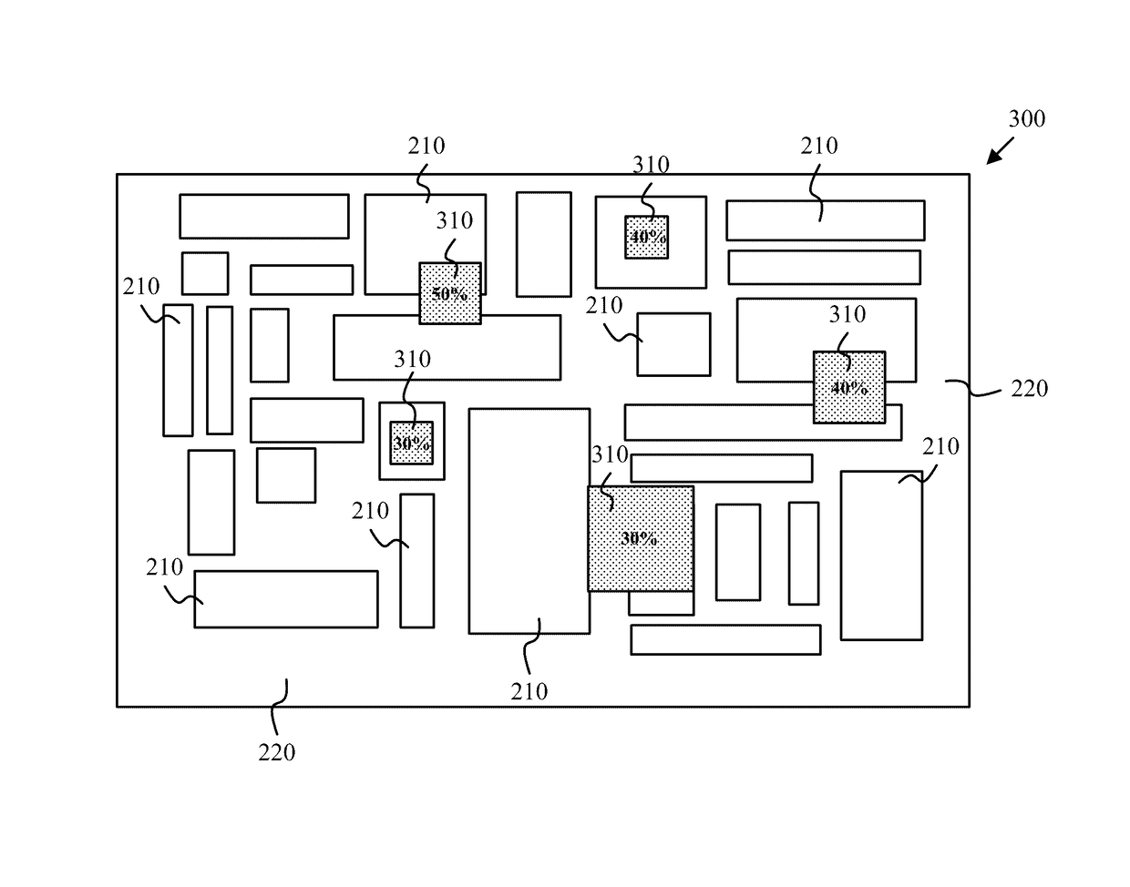
[0012]The embodiments disclosed herein enable improved IR-drop mitigation. It should be noted that references throughout this specification to features, advantages, or similar language herein do not imply that all of the features and advantages that may be realized with the embodiments disclosed herein should be, or are in, any single embodiment of the invention. Rather, language referring to the features and advantages is understood to mean that a specific feature, advantage, or characteristic described in connection with an embodiment is included in at least one embodiment of the present invention. Thus, discussion of the features, advantages, and similar language, throughout this specification may, but do not necessarily, refer to the same embodiment.

[0013]Furthermore, the described features, advantages, and characteristics of the invention may be combined in any suitable manner in one or more embodiments. One skilled in the relevant art will recognize that the invention may be p...


PUM


Abstract

A method, executed by one or more processors, includes receiving IR-drop information as a function of location for a placement for a plurality of circuit blocks corresponding to an integrated circuit, calculating a target density for decoupling capacitors as a function of location based on the IR-drop information, placing a plurality of decoupling capacitors according to the target density to provide placed decoupling capacitors. The placed decoupling capacitors may be locally clustered to improve decoupling performance. The method may also include incrementally moving circuit elements or placed decoupling capacitors to avoid collisions within one or more circuit blocks, and routing the integrated circuit. A corresponding computer program product and computer system are also disclosed herein.

Description

BACKGROUND OF THE INVENTION[0001]The present invention relates generally to designing electronic circuits such as integrated circuits, and more particularly to mitigating IR-drop in such circuits.[0002]A power distribution network for an integrated circuit distributes power and ground voltages from pad locations to all devices in an integrated circuit. Shrinking device dimensions, faster switching frequencies, and increasing power consumption in deep sub-micrometer technologies cause large switching currents to flow in the power and ground networks. Due to the resistance of the pathways constituting the network, there is a voltage drop across the network, commonly referred to as IR-drop. IR-drop reduces the effective voltage seen by integrated circuit elements and may negatively affect circuit performance.SUMMARY[0003]A method, executed by one or more processors, includes receiving IR-drop information as a function of location for a placement for a plurality of circuit blocks corres...

Claims


Application Information

Patent Timeline
Patent Type & Authority Patents(United States)
IPC IPC(8): G06F17/50
CPCG06F17/5081G06F17/5072G06F17/5077G06F2217/82G06F2119/10G06F30/392G06F30/394G06F2119/12G06F30/398
Inventor BAROWSKI, HARRYKEINERT, JOACHIMSAHA, SOURAVSTRACH, THOMAS
Owner INT BUSINESS MASCH CORP
Why Eureka
Try Eureka