Beam position monitor for energy recovered linac beams

a technology of beam position and beam beam, which is applied in the field of beam position monitors, can solve the problems of high cost of signal processing and high cost of time domain processing, and achieve the effects of accurate, reliable, and low cos

Active Publication Date: 2017-06-06
JEFFERSON SCI ASSOCS LLC
View PDF17 Cites 0 Cited by
  • Summary
  • Abstract
  • Description
  • Claims
  • Application Information

AI Technical Summary

Benefits of technology

[0005]The object of the present invention is to provide a lower cost method for monitoring the beam position in an energy recovered linac.SUMMARY OF THE INVENTION

Problems solved by technology

Although various non-intercepting electromagnetic beam position monitors have been developed for use in particle accelerators and beamlines, the cost of the signal processing to recover the beam position information can be substantially high.
As a result of requiring Giga-bit sampling acquisition hardware, time domain processing is very expensive.

Method used


Image

  • Beam position monitor for energy recovered linac beams
  • Beam position monitor for energy recovered linac beams
  • Beam position monitor for energy recovered linac beams

Examples


Embodiment Construction

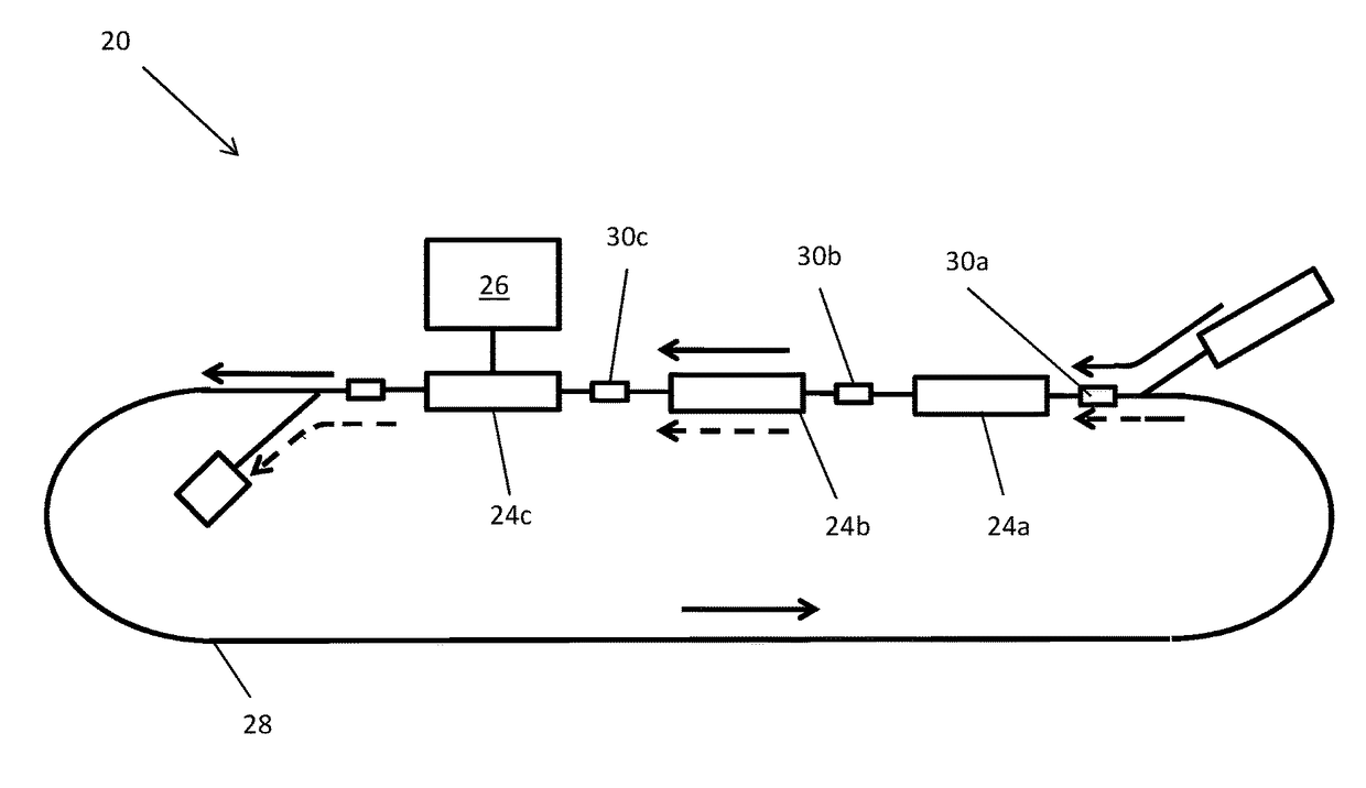
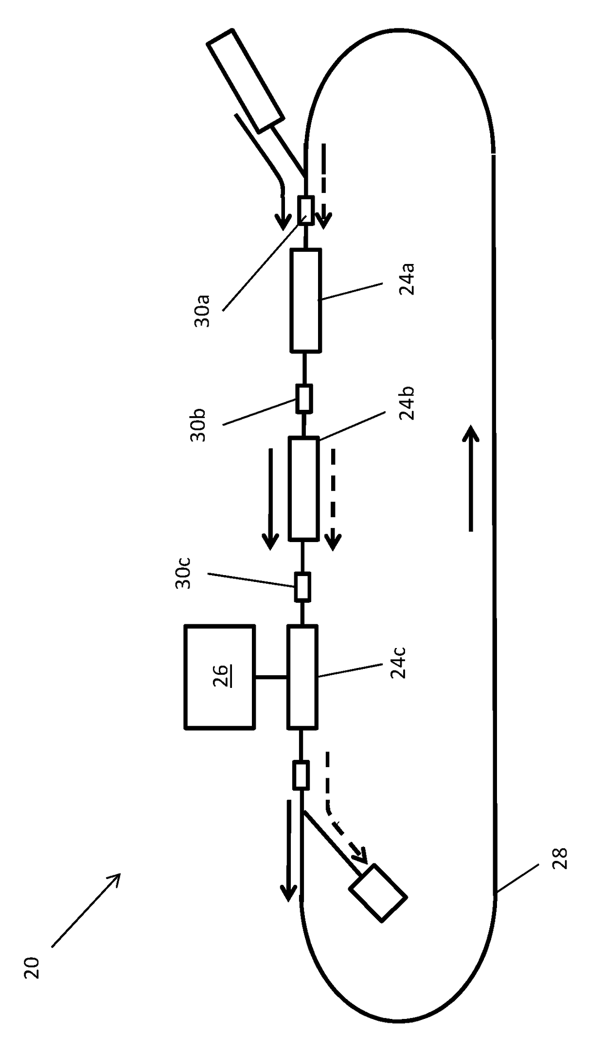
[0009]This invention is for a novel technique which makes use of in phase and quadrature (I / Q) demodulation techniques to separate out first and second pass beam in an energy recovered linac. The system will make use of either analog or digital based I / Q demodulation techniques in order to measure the relative amplitude of the signals from a position sensitive beam pickup such as a button, strip line or microstripline beam position monitor.

[0010]With reference to FIG. 1 there is shown an energy recovered linac 20 with a a plurality of RF cavities 24a, 24b, and 24c supplied by RF energy from an RF system 26 that accelerates particles around a path 28. The energy recovery linac 20 is an accelerator topology where the first pass beam extracts energy from the RF cavities 24a, 24b, and 24c and the second pass beam deposits an approximately equal amount of energy into the RF cavities. Thus the net energy from the RF system 26 that is deposited in the vector sum of the beams is very small ...


PUM


Abstract

A method of determining the beam position in an energy recovered linac (ERL). The method makes use of in phase and quadrature (I / Q) demodulation techniques to separate the pickup signal generated by the electromagnetic fields generated by the first and second pass beam in the energy recovered linac. The method includes using analog or digital based I / Q demodulation techniques in order to measure the relative amplitude of the signals from a position sensitive beam pickup such as a button, strip line or microstripline beam position monitor.

Description

GOVERNMENT LICENSE RIGHTS STATEMENT[0001]This invention was made with government support under Management and Operating Contract No. DE-AC05-06OR23177 awarded by the Department of Energy. The United States Government has certain rights in the invention.FIELD OF THE INVENTION[0002]The present invention relates to beam position monitors used in particle accelerators and beamlines and more particularly to a method for analog or digital based I / Q demodulation techniques in order to measure the relative amplitude of the signals from a position sensitive beam pickup such as a button, strip line or microstripline beam position monitor.BACKGROUND[0003]Although various non-intercepting electromagnetic beam position monitors have been developed for use in particle accelerators and beamlines, the cost of the signal processing to recover the beam position information can be substantially high. This is especially the case when the currents associated with periodically spaced beam bunches are con...

Claims


Application Information

Patent Timeline
Patent Type & Authority Patents(United States)
IPC IPC(8): H04L27/00H04L27/38A61N5/10
CPCH04L27/3827A61N5/1077A61N5/1049A61N5/1069A61N5/1048
Inventor POWERS, THOMASEVTUSHENKO, PAVEL
Owner JEFFERSON SCI ASSOCS LLC
Why Eureka
Try Eureka