
Acoustophoretic device for angled wave particle deflection

a technology of acoustophoretic devices and particle deflection, which is applied in the direction of instruments, separation processes, laboratory glassware, etc., can solve the problems of many settling ponds, low separation efficiency, and high cost of filtering, and achieve the effect of achieving the deflection of particles

Active Publication Date: 2017-06-06
FLODESIGN SONICS
View PDF297 Cites 25 Cited by
  • Summary
  • Abstract
  • Description
  • Claims
  • Application Information

AI Technical Summary

Benefits of technology

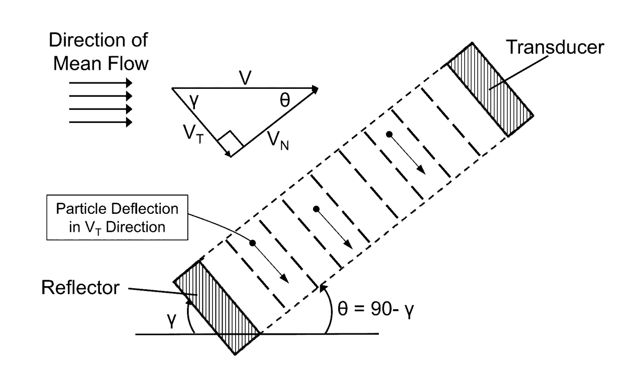
This patent is about a device and method to use sound waves to separate, fractionate, isolate, concentrate, wash, detect, or differentiate cells or particles in fluid suspension. The device includes an ultrasonic transducer and reflector that create an angled acoustic standing wave in a flow chamber with a particle path through it. This standing wave can deflect particles in a desired direction without trapping them. The device also has two inlets and outlets for fluid and washing fluid, allowing for a washing process. The technical effect is a more efficient and precise way to separate and manipulate cells or particles in fluid.

Problems solved by technology

Such filters are expensive and become clogged and non-functional as material is processed.
At these higher flow rates, trapping of the particles in the host fluid is decreased, thereby leading to decreased separation efficiency.
The rise of fracking techniques has led to many settling ponds and large costs for transportation of contaminated water.
Acoustophoresis provides, among other possible advantages, a solid-state, effective means of clarifying fracking, but the flow rates associated with such macro-scale acoustophoresis devices is still too low to be feasible.

Method used


Image

  • Acoustophoretic device for angled wave particle deflection
  • Acoustophoretic device for angled wave particle deflection
  • Acoustophoretic device for angled wave particle deflection

Examples


Embodiment Construction

[0051]The present disclosure may be understood more readily by reference to the following detailed description of desired embodiments and the examples included therein. In the following specification and the claims which follow, reference will be made to a number of terms which shall be defined to have the following meanings.

[0052]Although specific terms are used in the following description for the sake of clarity, these terms are intended to refer only to the particular structure of the embodiments selected for illustration in the drawings, and are not intended to define or limit the scope of the disclosure. In the drawings and the following description below, it is to be understood that like numeric designations refer to components of like function.

[0053]The singular forms “a,”“an,” and “the” include plural referents unless the context clearly dictates otherwise.

[0054]The term “comprising” is used herein as requiring the presence of the named component and allowing the presence o...


PUM

PropertyMeasurementUnit
angleaaaaaaaaaa
angleaaaaaaaaaa
frequencyaaaaaaaaaa

Abstract

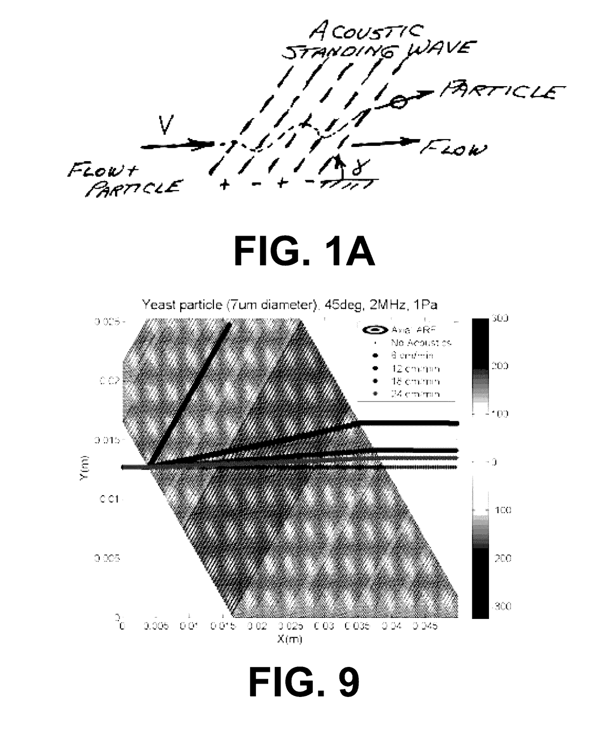
Devices for separating materials from a host fluid are disclosed. The devices include a flow chamber, an ultrasonic transducer, and a reflector. The ultrasonic transducer and reflector create an angled acoustic standing wave oriented at an angle relative to the direction of mean flow through the flow chamber. The angled acoustic standing wave results in an acoustic radiation force having an axial force component that deflects the materials, so that the materials and the host fluid can thus be separated. The angled acoustic standing wave can be oriented at an angle of about 20° to about 70° relative to the direction of mean flow through the flow chamber to deflect, collect, differentiate, or fractionate the materials from the fluid flowing through the device at flow rates of about 400 mL / min up to about 700 mL / min.

Description

CROSS-REFERENCE TO RELATED APPLICATIONS[0001]This application claims priority to U.S. Provisional Patent Application Ser. No. 62 / 316,933, filed on Apr. 1, 2016; and to U.S. Provisional Patent Application Ser. No. 62 / 154,690, filed on Apr. 29, 2015, the disclosures of which are hereby fully incorporated by reference in their entireties.BACKGROUND[0002]In the medical field, it often is desirable to separate low concentration cells from a fluid mixture with no harm to the cells, wash cells, concentrate cells in a fluid mixture, differentiate cells based on key parameters, or even fractionate many different types of cells. Such processes are key in the development of possible cures to many common diseases. It may also be desirable to separate particles or cells different in size, density and or acoustic contrast factor through the use of an acoustic field where the particles may be separated from each other as well. Examples include the separation of live from dead cells, and the separa...

Claims


Application Information

Patent Timeline
Patent Type & Authority Patents(United States)
IPC IPC(8): C12N13/00G01N29/00C12M1/00B01D21/28A61M1/36B01D21/00G01N15/10G01N15/14G01N15/00
CPCC12N13/00A61M1/3678B01D21/283C12M47/04G01N15/1484B01L2400/0436B01L2400/0439G01N2015/0053G01N2015/1006G01N2015/149B01L3/502761B01L2300/0864B01L2300/0867G01N15/149
Inventor LIPKENS, BARTPRESZ, WALTER M.CHITALE, KEDARKENNEDY, III, THOMAS J.ROSS-JOHNSRUD, BEN
Owner FLODESIGN SONICS
Learn More