
Radiographic image capturing system and console

a technology of radiographic images and consoles, applied in the field of radiographic image capturing systems and consoles, can solve the problems of operator error in performing image quality adjustment, image quality adjustment, operator becoming unable to understand which image, etc., and achieve the effect of accurate performing image quality adjustmen

Active Publication Date: 2017-05-30
KONICA MINOLTA INC
View PDF6 Cites 15 Cited by
  • Summary
  • Abstract
  • Description
  • Claims
  • Application Information

AI Technical Summary

Benefits of technology

This configuration ensures that radiographic images are accurately correlated with imaging order information, preventing misunderstandings and ensuring that image quality adjustments are consistently applied, thereby enhancing system usability and reducing errors.

Problems solved by technology

On the other hand, as to an operator who is not accustomed to a work(s), if the radiographic image capturing system and / or the console are configured to allow the operator to perform imaging of all the radiographic images first and then execute the image quality adjustment of all the radiographic images at once, there may be occurred a problem that the operator becomes unable to understand which of the images has been or has not been subjected to the image quality adjustment.
Concretely, for example, even the operator accustomed to the works may wrongly perform the image quality adjustment to the radiographic image which has been taken by another operator and is displayed on the console, when the operator and the another operator share one (1) console, or may forget to perform the image quality adjustment in the misguided belief that the radiographic image has been taken by the another operator, though the radiographic image has been taken by the operator himself / herself.
There may also be a case that the another operator wrongly performs the image quality adjustment to the radiographic image which has been taken by the operator himself / herself.

Method used


Image

  • Radiographic image capturing system and console
  • Radiographic image capturing system and console
  • Radiographic image capturing system and console

Examples


example 1

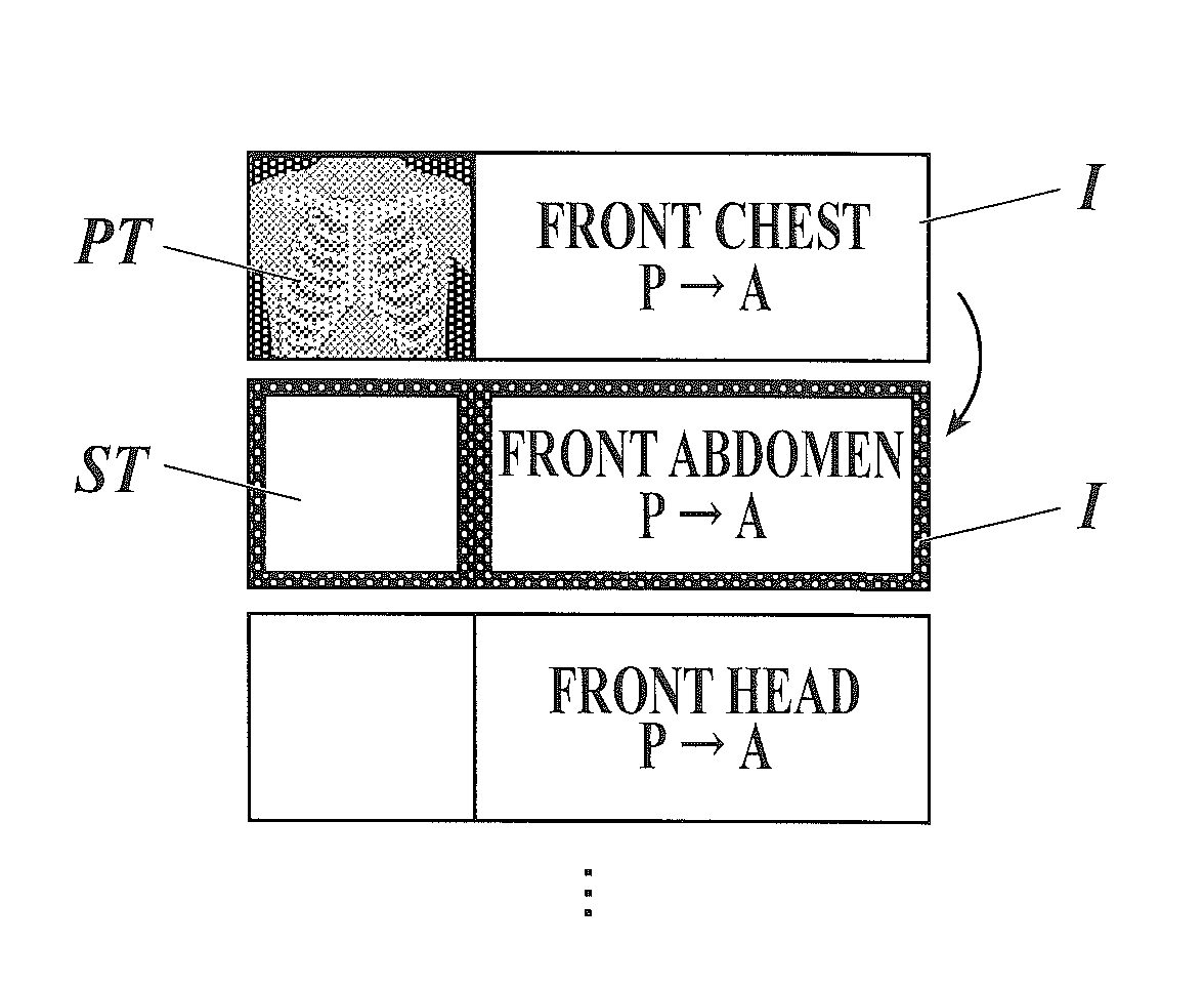
[0144]There is considered as an example a case where an operator such as a radiologist using the radiographic image capturing system 50 and the like is not accustomed to the above-described works, and there is only the second transition mode as the transition mode of the focus display by the console 58, which independently moves each of the focus display of the icon I and the focus display of the thumbnail image PT.

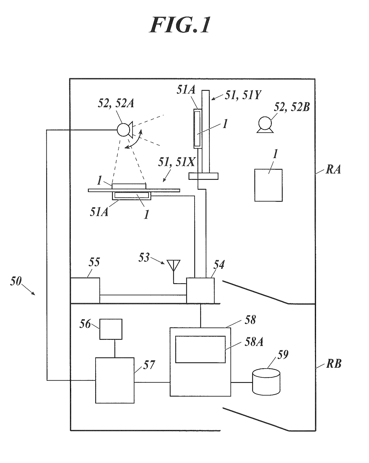
[0145]In this case, the focus display of the icon I and the focus display of the thumbnail image PT are moved separately while the operator goes back and forth between the imaging room RA where imaging is performed and the front room RB (see FIG. 1). For this reason, as described above, there is a possibility that the operator who is not accustomed to the works becomes unable to understand which of the images has not been subjected to the image quality adjustment. There is also a possibility that the operator replaces the images with one another by manual operation, and w...

example 2

[0150]On the other hand, in the case that an operator such as a radiologist using the radiographic image capturing system 50 and the like is accustomed to the above-described works, the operator confirms only necessity of retake by looking at the preview image P_PRE displayed on the screen H2 of the console 58, and performs a series of imaging processes first, while postponing the confirming process of the radiographic image P. The operator often wants to perform these confirming processes simultaneously later. Such processing is more convenient also for a patient, because a waiting time of the patient as an object is reduced and thereby the imaging will end early.

[0151]In such as case, if the radiographic image capturing system 50 and the console 58 are configured as described in the embodiment, by selecting and setting the second transition mode (see FIGS. 14A and 14B) as the transition mode of the focus displays of the console 58, it becomes possible to perform the setting of the...

example 3

[0165]With respect to the radiographic image capturing system 50 illustrated in FIG. 1, the case where one (1) person as the operator such as the radiologist goes back and forth between the imaging room RA and the front room RB to perform the imaging, the image quality adjusting process and / or the confirming process, is described. However, for example, there may also be a case where the works are shared so that one operator (e.g. a radiologist having little experience) performs the imaging and another operator (e.g. an upper class radiologist) performs the image quality adjusting process and the confirming process.

[0166]In the case that the operator who executes the imaging in the imaging room RA is different from the operator who executes the confirming process of the radiographic image P and the like by using the console 58 as described above, the operator executing the imaging is expected to wish to successively image the radiographic images while entrusting the different operato...


PUM


Abstract

A console includes a display section. The console performs a focus display of the icon corresponding to the imaging order information regarding a currently-performed imaging, and when the imaging ends, moves the focus display of the icon to the icon of a next imaging. The console performs a focus display of the thumbnail image, and after a confirming process or when a predetermined time has passed, moves the focus display of the thumbnail image to a position at which the thumbnail image of the next imaging to be displayed on the display section. The console includes a first transition mode in which focus display transitions of the icon and thumbnail image are performed concurrently, and a second transition mode in which each of them is independently from each other. The transition mode of the focus display is capable of being switched between the first and second transition modes.

Description

CROSS REFERENCE[0001]The present invention claims priority under 35 U.S.C. §119 to Japanese Application No. 2013-221700 filed Oct. 25, 2013, the entire content of which is incorporated herein by reference.BACKGROUND OF THE INVENTION[0002]Field of the Invention[0003]The present invention relates to a radiographic image capturing system and a console, and especially to a console capable of displaying an icon corresponding to imaging order information, thumbnail image of a radiographic image, etc., and a radiographic image capturing system equipped with the console.[0004]Description of Related Art[0005]Heretofore, in a field of a radiographic image capturing system which irradiates an object with radiation such as an X-ray to capture a radiographic image for the purpose of disease diagnosis or the like, there has been increased a case of using a radiographic image capturing apparatus (Flat Panel Detector: FPD) in which radiation detecting elements, each converting irradiated radiation ...

Claims


Application Information

Patent Timeline
Patent Type & Authority Patents(United States)
IPC IPC(8): A61B6/00G06F3/0481G06F3/0484G06F3/0482
CPCA61B6/5294A61B6/563G06F3/0482G06F3/04817G06F3/04842A61B6/463A61B6/465A61B6/5211
Inventor HAYASHI, NAOKI
Owner KONICA MINOLTA INC
Learn More