
Fiber optic display apparatus and methods of osillating illuminated optical fibers

a technology of optical fibers and fiber optic displays, applied in the direction of illuminated signs, display means, instruments, etc., can solve the problems of inherently limited range of motion, responsiveness, and limited illumination options of optical fibers

Active Publication Date: 2017-05-23
SPANGLER THOMAS MARK
View PDF31 Cites 1 Cited by
  • Summary
  • Abstract
  • Description
  • Claims
  • Application Information

AI Technical Summary

Benefits of technology

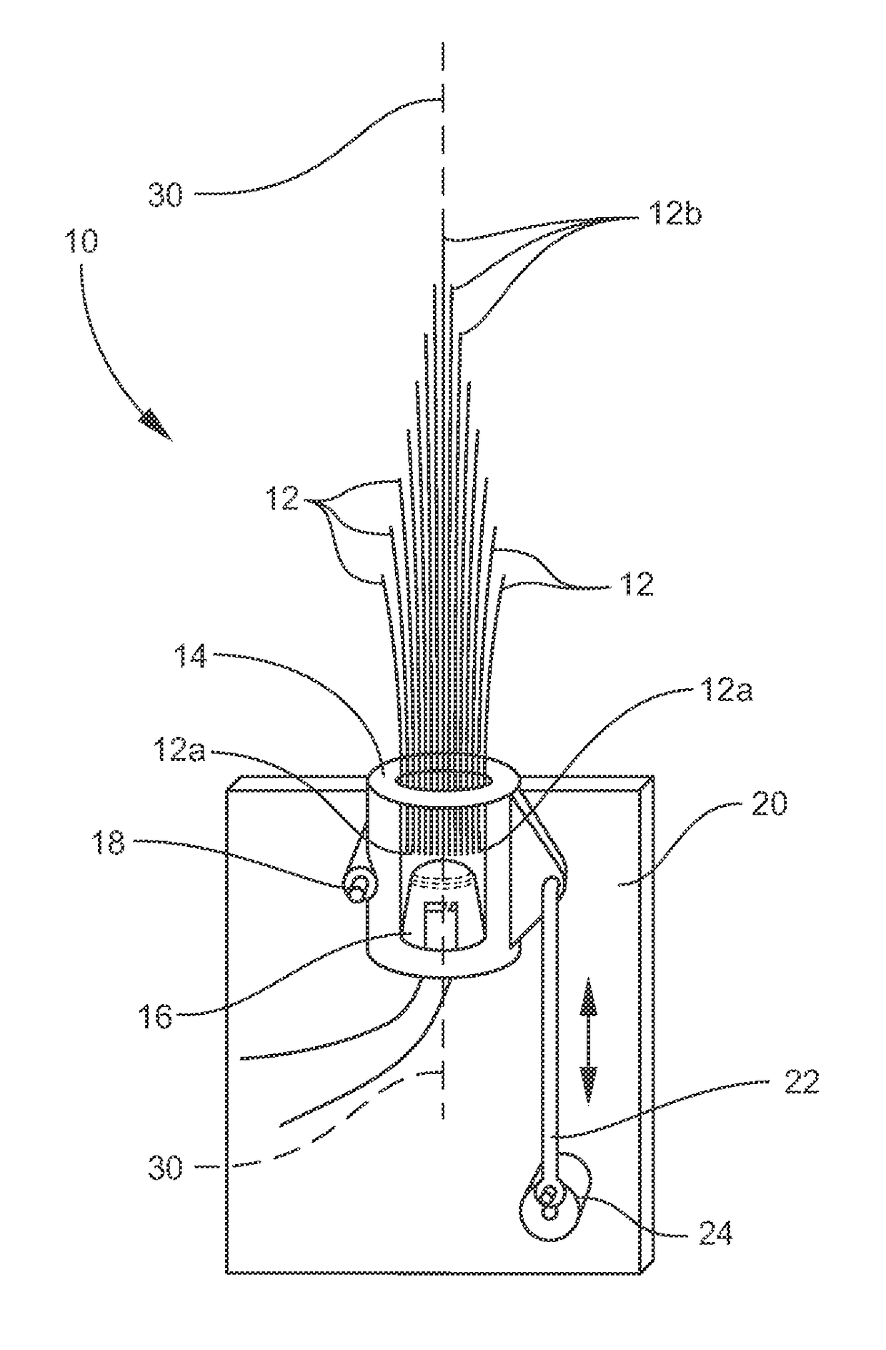
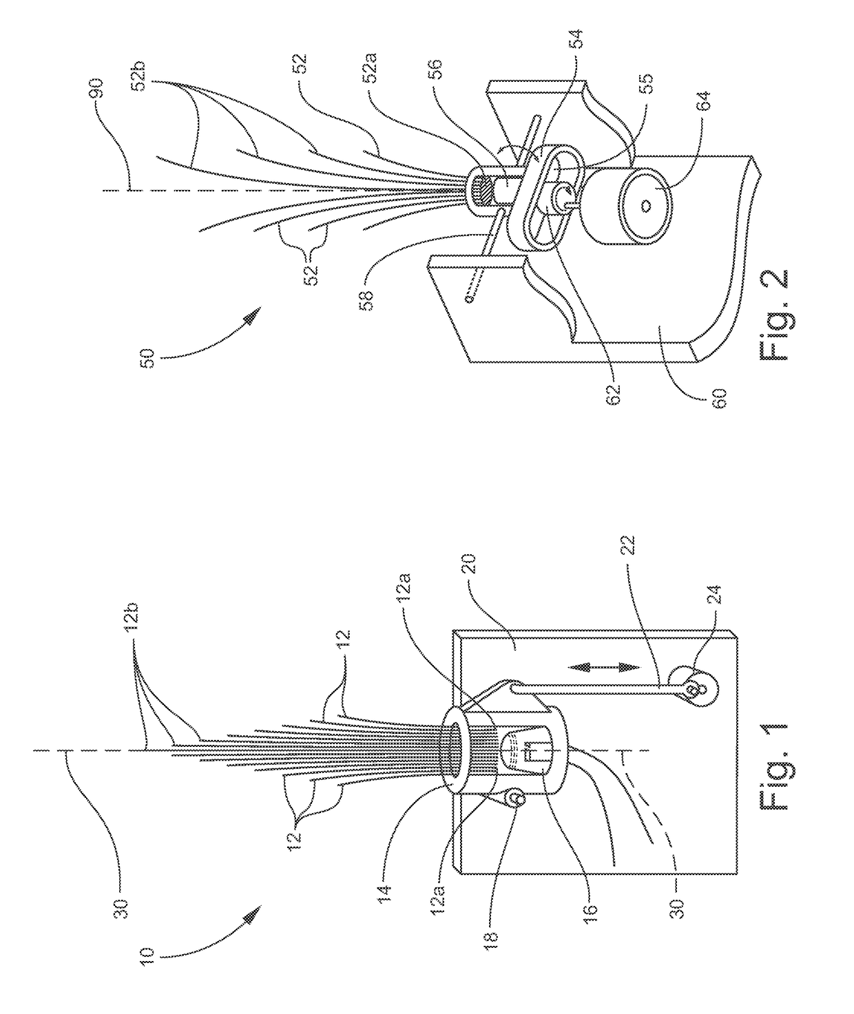
The present invention provides an apparatus for creating unique and visually stimulating optical displays and light patterns in space using the oscillation of illuminated optical fibers. The invention allows for the creation of many flexible design options and can provide greater, more effective responsiveness of all the optical fibers. The invention also allows the holding member and fibers to move in roughly the same manner through space, regardless of their orientation to gravity. The invention can require less power to achieve the desired visual effects and can also allow for the creation of complex multi-directional moving displays in a more predictable and organized manner.

Problems solved by technology

While this axial motion of the holder and fibers can create unique visual effects, the range of motion, responsiveness, and illumination options of the optical fibers is inherently limited.

Method used


Image

  • Fiber optic display apparatus and methods of osillating illuminated optical fibers
  • Fiber optic display apparatus and methods of osillating illuminated optical fibers
  • Fiber optic display apparatus and methods of osillating illuminated optical fibers

Examples


embodiment 10

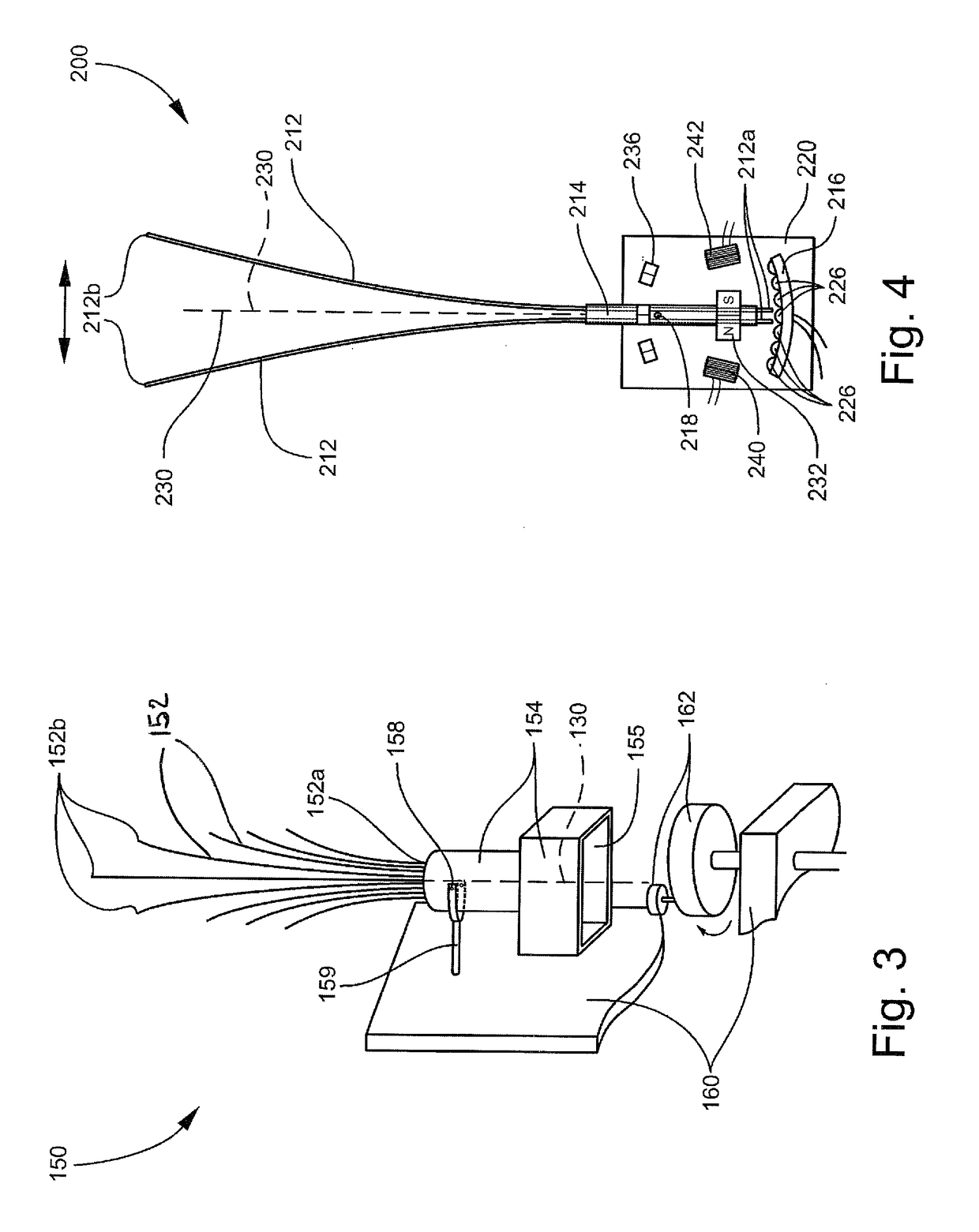
[0048]The illuminated fiber ends 212a can be exposed to and illuminated by a stationary light source 216, such as a multi-colored LED array 216 of multiple individual lights 226 affixed to the housing 220, as shown in FIG. 4. Alternatively, the light source 216 can be an incandescent bulb, mirror, prism, lens, or array thereof. As the holding member 214 is moved throughout its range of motion, the illuminated fiber ends 212a are exposed to the stationary light source 216, causing light to be emitted from the display end 212b of the fibers 212 allowing for color changes within the fibers 212 as they sweep across the multi-colored array 216 corresponding to the individual colored light elements 226 of the array 216. Alternatively, the holding member 214 can contain the light source 216, such as in the embodiment 10 illustrated in FIG. 1, in which the housing 14 contains the light source 16 to illuminate the fibers 12.

[0049]The holding member 214 is freely secured to a pivot point axis...

embodiment 650

[0062]An optical fiber display device according to another preferred embodiment of the invention is illustrated in FIG. 15 and shown generally at reference numeral 650. This embodiment 650 of the invention utilizes a magnetic coupling method of oscillation, as in the device 250 illustrated in FIG. 6, combined with a second simultaneous movement of the embodiment 650, about an axis 682 that is non-parallel to the longitudinal axis 662 of the holding member 654 and relatively perpendicular to the pivot point axis 658 of the holding member 654.

[0063]The device 650 comprises optical fibers 652, an electromagnetic coil 680, and light source(s) affixed to the fiber holding member 654. The holding member 654 is functionally attached to the housing 660 and movable about the pivot point axis 658. The pivot point axis 658 is relatively perpendicular to the longitudinal axis 662 of the holding member 654 and optical fibers 652 within the holding member 654. Permanent magnets 670, 672, 674, 676...


PUM


Abstract

A fiber optic display device reciprocates fiber optics to create decorative optical fiber light displays. The device can include one or more optical fibers contained at one end by a holding member and left suspended freely at the other end. The holding member and optical fibers are functionally attached about a pivot point axis that is across the longitudinal axis of the fibers and the holding member, to a housing. A light source can be affixed to either the holding member or the housing, opposite the freely suspended optical fiber ends, and is oriented to expose and illuminate the optical fibers. A drive means causes the holding member and optical fibers to reciprocate back and forth about the pivot point axis of the holding member.

Description

CROSS REFERENCE TO RELATED APPLICATIONS[0001]This application is a continuation in part of U.S. patent application Ser. No. 13 / 327,344, filed Dec. 15, 2011, which is incorporated herein and claims priority to U.S. Provisional Patent Application No. 61 / 423,572, filed Dec. 15, 2010, which is also incorporated herein.TECHNICAL FIELD AND BACKGROUND OF THE INVENTION[0002]The present invention relates to decorative fiber optic lamps, toys, and displays, and various new methods of moving and manipulating illuminated optical fibers. Fiber optics have been used for decades to create visually stimulating displays and decorations, even incorporating movement to enhance the visual effects. The type of movement has been thus far about an axis running longitudinally through the fibers within their holder. While this axial motion of the holder and fibers can create unique visual effects, the range of motion, responsiveness, and illumination options of the optical fibers is inherently limited. A ne...

Claims


Application Information

Patent Timeline
Patent Type & Authority Patents(United States)
IPC IPC(8): F21V8/00G09F13/18
CPCG02B6/0005G09F13/18
Inventor SPANGLER, THOMAS MARK
Owner SPANGLER THOMAS MARK
Learn More