
Vibrator, oscillator, electronic device for controlling internal resonance between inherent vibration modes

a technology of internal resonance and oscillator, which is applied in the direction of oscillator, force measurement, instruments, etc., can solve the problems of increasing non-linearity, difficult to symmetrically form the vibrating arm, etc., and achieves the effect of small size, low resonance frequency, and increasing the effect of invention

Active Publication Date: 2017-05-16
SEIKO EPSON CORP
View PDF16 Cites 3 Cited by
  • Summary
  • Abstract
  • Description
  • Claims
  • Application Information

AI Technical Summary

Benefits of technology

[0037]The high-order mode has a greater influence on the main vibration as the order becomes smaller, and thus the effect of the invention further increases.
[0038]In the vibrator according to the application example, it is preferable that the main vibration is the first direction reverse-phase mode.
[0039]With this configuration, a vibrator is obtained which is capable of realizing a high Q value and has a small CI value.
[0040]In the vibrator according to the application example, it is preferable that the high-order mode includes at least one of second-order modes of the first direction reverse-phase mode, the first direction in-phase mode, the third direction reverse-phase mode, and the third direction in-phase mode.
[0041]Such an inherent mode is a vibration which has a low resonance frequency among high-order modes, and particularly has a tendency to be coupled to the main vibration (first direction reverse-phase mode). Therefore, the effect of the invention further increases.
[0042]In the vibrator according to the application example, it is preferable that when seen in plan view, the vibrating arm includes: a weight portion; and an arm which is disposed between the weight portion and the base portion, when a length of the arm along a direction in which the base portion and the vibrating arm are lined up is set to L, a relation of L≦0.9 mm is satisfied, when a thickness of the arm is set to T, the relation of 50 μm≦T≦150 μm is satisfied, when a width of the arm along a direction in which the pair of vibrating arms are lined up is set to W, a relation of W≦60 μm is satisfied, when a length of the weight portion along the direction in which the base portion and the vibrating arm are lined up is set to L′, a relation of L′ / L≦0.5 is satisfied, and when a width of the weight portion along the direction in which the pair of vibrating arms are lined up is set to W″, a relation of L′<W″ is satisfied.

Problems solved by technology

With this configuration, a vibrator element is obtained which is relatively small in size, and there is a tendency for non-linearity to increase due to symmetry being lost from the shape of the vibrator element.
With this configuration, it becomes difficult to symmetrically form the vibrating arm.

Method used


Image

  • Vibrator, oscillator, electronic device for controlling internal resonance between inherent vibration modes
  • Vibrator, oscillator, electronic device for controlling internal resonance between inherent vibration modes
  • Vibrator, oscillator, electronic device for controlling internal resonance between inherent vibration modes

Examples


first embodiment

[0090]First, a vibrator according to a first embodiment of the invention will be described.

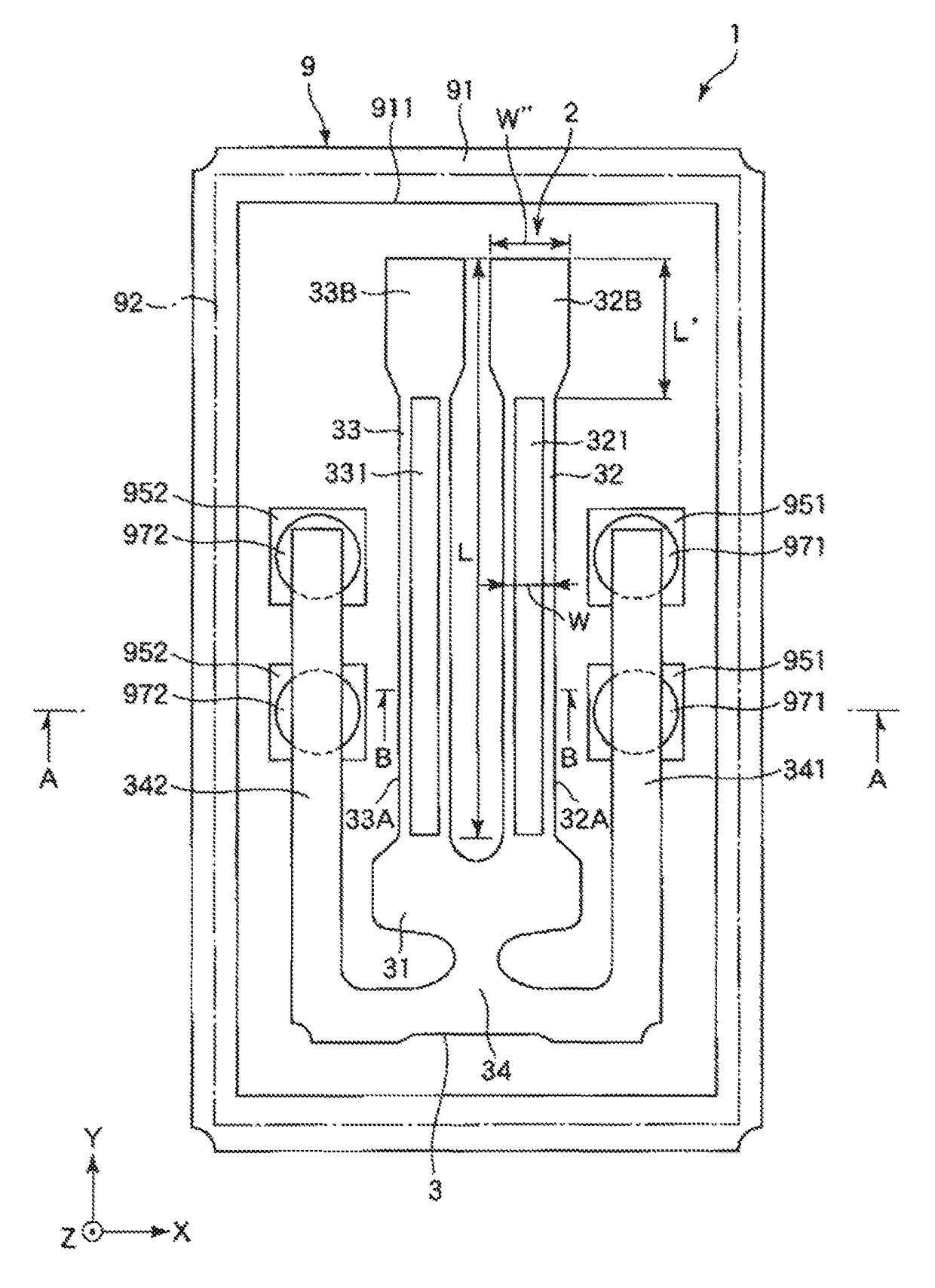
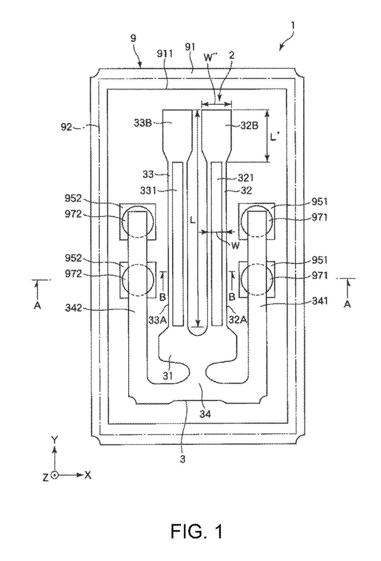
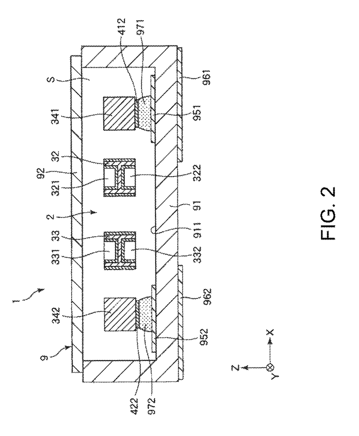
[0091]FIG. 1 is a plan view illustrating a vibrator according to the first embodiment of the invention. FIG. 2 is a cross-sectional view taken along line A-A of FIG. 1. FIG. 3 is a cross-sectional view taken along line B-B of FIG. 1. FIGS. 4A to 4F are plan views illustrating inherent vibration modes of a vibrator element. FIG. 5 is a graph illustrating a relationship between Δω and a Q value.

[0092]A vibrator 1 shown in FIGS. 1 and 2 includes a package 9 and a vibrator element 2 housed in the package 9.

[0093]Hereinafter, the package 9 and the vibrator element 2 will be described in order.

Package 9

[0094]As shown in FIGS. 1 and 2, the package 9 includes a box-shaped base 91 having a concave portion 911 which is open to the upper surface, and a plate-like lid 92, bonded to the base 91, which blocks an opening of the concave portion 911. Such a package 9 has a hermetic housing space S formed by th...

specific example 3

[0151]For example, when k1=−1 and k2=3, the relation of ω1′=3ω2 is established, and the following Expression (20) can be derived from Expression (8). When k1=3 and k2=2, the relation of (ω1′=ω2 / 3 is established, and the following Expression (21) can be derived from Expression (8).

[0152]Δω=3⁢ω2-ω1ω1(20)Δω=ω23-ω1ω1(21)

Specific Example 4: m=4, n=3

[0153]For example, when k1=−2 and k2=k3=1, the relation of ω1′=(ω2+ω3) / 2 is established, and the following Expression (22) can be derived from Expression (8). When k1=−2, k2=1, and k3=−1, ω1′=(ω2−ω3) / 2 is established, and the following Expression (23) can be derived from Expression (8). When k1=−1, k2=2, and k3=1, the relation of ω1′=2ω2+ω3 is established, and the following Expression (24) can be derived from Expression (8). When k1=−1, k2=2, and k3=−1, the relation of ω1′=2ω2−ω3 is established, and the following Expression (25) can be derived from Expression (8).

[0154]Δω=ω2+ω32-ω1ω1(22)Δω=ω2-ω32-ω1ω1(23)Δω=2⁢ω2+ω3-ω1ω1(24)Δω=2⁢ω2-ω3-ω1ω1(25)

specific example 4

[0155]In this case, the following Expression (26) can be derived from Expression (7).

[0156]ω1′=k2⁢ω2+k3⁢ω3+k4⁢ω4-k1(26)

[0157]For example, when k1=−1 and k2=k3=k4=1, the relation of ω1′=ω2+ω3+ω4 is established, and the following Expression (27) can be derived from Expression (8). When k1=k3=−1 and k2=k4=1, the relation of ω1′=ω2−ω3+ω4 is established, and the following Expression (28) can be derived from Expression (8). When k1=k4=−1 and k2=k3=1, the relation of ω1′=ω2+ω3−ω4 is established, and the following Expression (29) can be derived from Expression (8). When k1=k3=k4=−1 and k2=1, the relation of ω1′=ω2−ω3−ω4 is established, and the following Expression (30) can be derived from Expression (8).

[0158]Δω=ω2+ω3+ω4-ω1ω1(27)Δω=ω2-ω3+ω4-ω1ω1(28)Δω=ω2+ω3-ω4-ω1ω1(29)Δω=ω2-ω3-ω4-ω1ω1(30)

[0159]Next, some specific examples will be given of a case where the inherent vibration mode is specified.


PUM

PropertyMeasurementUnit
vibration frequencyaaaaaaaaaa
thicknessaaaaaaaaaa
vibration frequencyaaaaaaaaaa

Abstract

A vibrator includes a vibrator element and a base on which the vibrator element is installed. In addition, when n is set to a natural number equal to or greater than 2, and j is set to a natural number equal to or greater than 1 and equal to or less than n, the vibrator element includes n inherent vibration modes having resonance frequencies different from each other, and when a resonance frequency of a main vibration of the vibrator element in the n inherent vibration modes is set to ω1 in a relationship between an arbitrary integer kj and a resonance frequency ωj corresponding to each of the n inherent vibration modes, the following three expressions are all satisfied.Δω≡(∑j=2n⁢kj⁢ωj-k1-ω1) / ω1ω1≥0.1⁢⁢3≤∑j=1n⁢⁢kj≤10

Description

BACKGROUND[0001]1. Technical Field[0002]The present invention relates to a vibrator, an oscillator, a real-time clock, an electronic device and a moving object.[0003]2. Related Art[0004]Hitherto, a tuning fork type vibration element using a quartz crystal has been known. Such a vibration element includes a base portion and a pair of vibrating arms, and is configured to flexurally vibrate using a flexural reverse-phase mode (hereinafter, referred to as an X-axis reverse-phase mode) in which the pair of vibrating arms alternately repeat approach and separation to and from each other, when seen in plan view, as a main vibration. In addition, in the field of such a vibration element, various configurations for reducing the vibration leakage (loss of elastic energy leaking outside of the vibration element) of the main vibration have been disclosed. For example, JP-A-2002-261575 discloses that the vibration leakage of the main vibration is reduced by forming notches on both sides of the b...

Claims


Application Information

Patent Timeline
Patent Type & Authority Patents(United States)
IPC IPC(8): H03B5/30H03B5/32H03H9/21H03H9/05G01L1/10H03H9/19H03H9/215
CPCH03H9/19G01L1/106H03B5/32H03H9/0547H03H9/21H03H9/215
Inventor YAMADA, AKINORIYOSHIDA, SHUHEIKIKUCHI, TAKAYUKI
Owner SEIKO EPSON CORP
Learn More