
Power conversion device and control method thereof

a power conversion device and control method technology, applied in power conversion systems, emergency power supply arrangements, electrical equipment, etc., can solve problems such as security problems and complicated circuit designs of conventional power conversion devices, and achieve stable output voltage, simplify complicated circuit design, and great utility value

Active Publication Date: 2017-05-16
DELTA ELECTRONICS INC
View PDF6 Cites 0 Cited by
  • Summary
  • Abstract
  • Description
  • Claims
  • Application Information

AI Technical Summary

Benefits of technology

The present invention provides a power conversion device that can automatically switch between high-voltage AC power and low-voltage DC power to output a stable voltage to the next stage system. This simplifies the circuit design and control method, making the device more secure and efficient in managing power. Overall, the technical solution of this patent has significant benefits and utilization value in the industry.

Problems solved by technology

However, conventional circuit designs of the power conversion devices are complicated and have security issues because they have to adapt to different input signals and correspondingly control their circuit operations.

Method used


Image

  • Power conversion device and control method thereof
  • Power conversion device and control method thereof
  • Power conversion device and control method thereof

Examples


Embodiment Construction

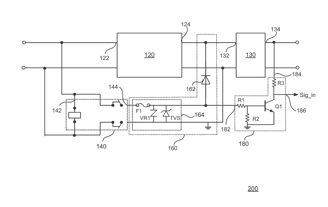
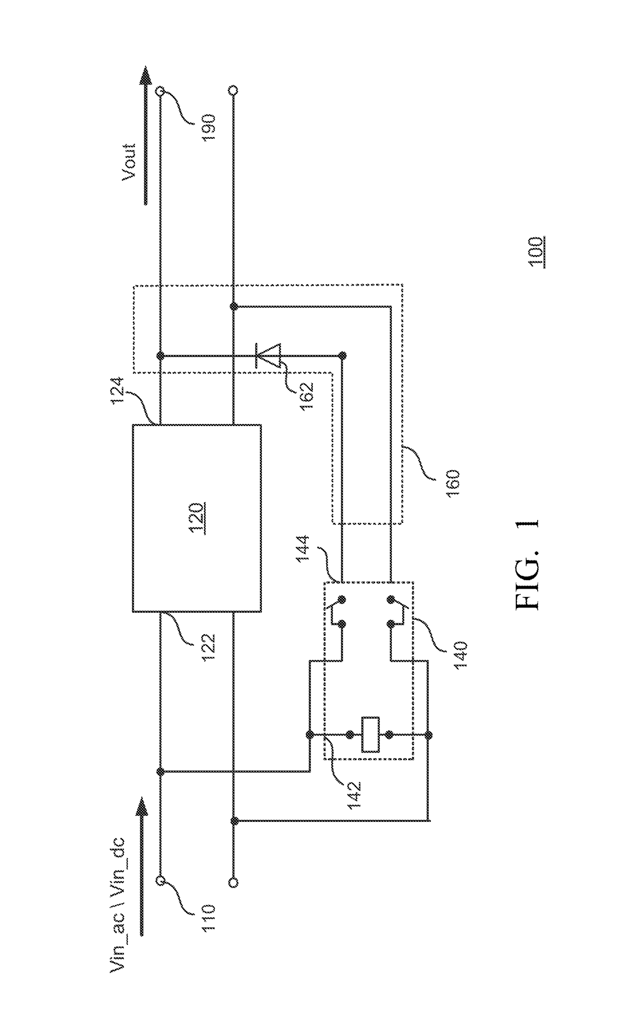
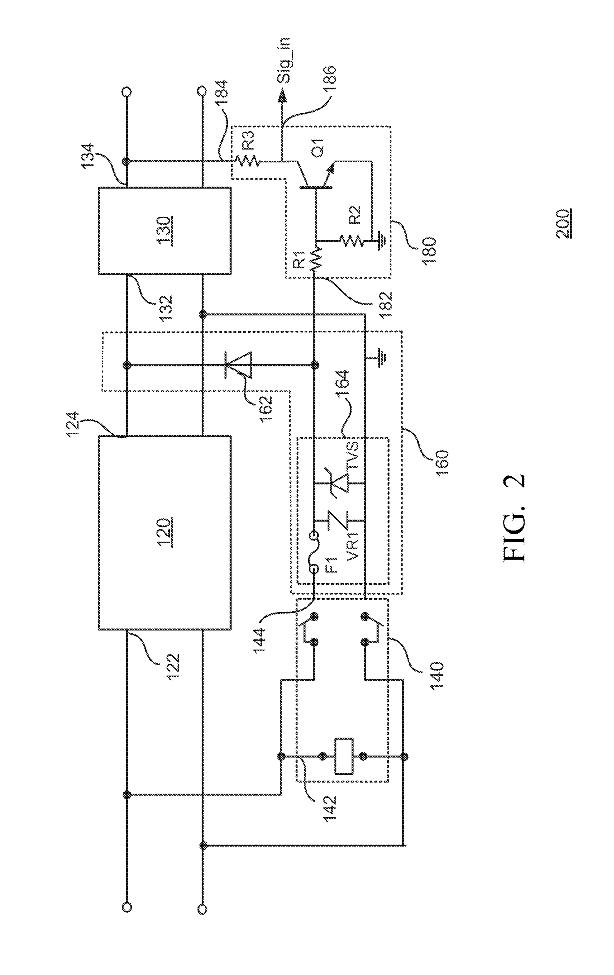
[0026]Specific embodiments of the present invention are further described in detail below with reference to the accompanying drawings, however, the embodiments described are not intended to limit the present invention and it is not intended for the description of operation to limit the order of implementation. Moreover, any device with equivalent functions that is produced from a structure formed by a recombination of elements shall fall within the scope of the present invention. In addition, in accordance with the standard practice in the industry, various features are not drawn to scale. In fact, the dimensions of the various features may be arbitrarily increased or reduced for clarity of discussion. In the specification, same units will be described with same labels for the sake of understanding.

[0027]Terms used in the specification and the claims have general meaning, unless it is particularly noted, of the terms used in this field, in the content of the description and in the s...


PUM


Abstract

A power conversion device is disclosed herein. The power conversion device includes an AC-DC conversion unit, a switching unit and a bypass circuit. The AC-DC conversion unit is configured to receive an AC input voltage via a power input terminal, and output a DC output voltage to a power output terminal according to the AC input voltage. The switching unit is configured to be switched off according to the AC input voltage received from the power input terminal, and to be switched on according to a DC input voltage received from the power input terminal. The bypass circuit is configured to receive the DC input voltage via the switching unit, and output the DC output voltage to the power output terminal according to the DC input voltage.

Description

RELATED APPLICATIONS[0001]This application claims priority to Taiwan Application Serial Number 104113155 filed on Apr. 24, 2015, which is herein incorporated by reference.BACKGROUND[0002]Field of Invention[0003]The present invention relates to an electrical power device. More particularly, the present invention relates to a power conversion device.[0004]Description of Related Art[0005]Recently, in order to provide backup direct current (DC) power to a next stage system when alternating current (AC) power of mains electricity is abnormal, a variety of power conversion devices are required to transmit high-voltage AC signals and low-voltage DC signals through different lines.[0006]However, conventional circuit designs of the power conversion devices are complicated and have security issues because they have to adapt to different input signals and correspondingly control their circuit operations.[0007]Therefore, how to simplify the design of the power conversion devices and efficiently...

Claims


Application Information

Patent Timeline
Patent Type & Authority Patents(United States)
IPC IPC(8): H02J9/06H02M1/10H02M7/04H02M7/217H02M1/32
CPCH02M7/04H02M1/10H02M1/32
Inventor LU, LIANG-WEIPENG, YUNG-WEILIN, JUI-LING
Owner DELTA ELECTRONICS INC
Learn More