
Cooling device having air guide for a radiator of an automobile engine

Active Publication Date: 2017-05-09
RENAULT SAS
View PDF9 Cites 7 Cited by
  • Summary
  • Abstract
  • Description
  • Claims
  • Application Information

AI Technical Summary

Benefits of technology

This patent proposes an improved cooling system for automotive radiators that is adapted to various vehicle models. The system includes an air guide with separate front and rear parts that can be easily attached to each other. The cooling flaps are designed to be removable and placed inside the air guide. The system has a reduced risk of damage to the radiator in the event of a collision. The flaps are positioned in a lower section of the air guide to provide good resistance to front impacts. The use of the flaps module can help decrease CO2 emissions in vehicles without a tax on emissions. The overall fluidtightness of the air guide is improved when compared to conventional vehicles without controlled flaps.

Problems solved by technology

This is because it is known that letting air in over a front bumper impairs the aerodynamic drag coefficient SCx and therefore increases the CO2 emissions of the vehicle.
Motor manufacturers have therefore sought to position moving flaps on the air circuit, but the positioning of these moving flaps presents numerous problems in the compact environment of the front end of a vehicle where there are numerous other requirements that have to be met, notably in terms of impact protection, notably pedestrian impact.
Thus, a moving flap positioned in or too close to the air intake grille is unsatisfactory: there is a risk that the flap will be damaged in the slightest impact, with high replacement costs involved in the repair.
A flap borne by or incorporated into the technical front panel of the vehicle presents problems of fragility and what is more does not lend itself well to a construction that is standardized across various models given that the technical front panel is very closely tied to the design of the vehicle, made entirely of sheet metal and expensive.
This construction has the disadvantage of being specifically tied to each model of vehicle and of leaving the shut-off flaps exposed to all impacts, including low-speed impacts.

Method used


Image

  • Cooling device having air guide for a radiator of an automobile engine
  • Cooling device having air guide for a radiator of an automobile engine
  • Cooling device having air guide for a radiator of an automobile engine

Examples


Embodiment Construction

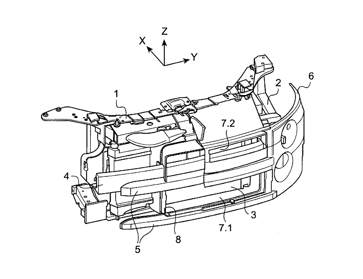
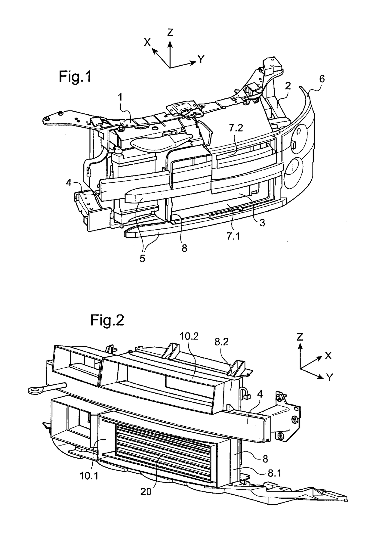
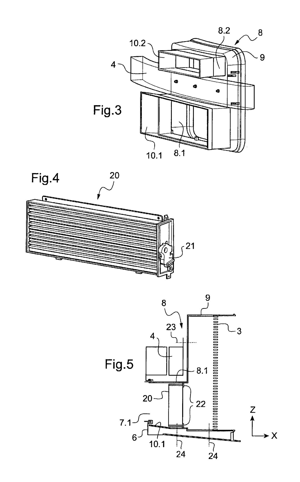
[0026]FIG. 1 illustrates the front of the engine compartment at the front of a vehicle of a conventional type to which the invention may be applied. From the rear forward, there are:[0027]The technical front end 1 which acts as a vertical support for a certain number of components and is fixed securely to structural elements of the chassis, for example to components connected to the chassis frame side rails 2.[0028]The vertical radiator 3, fixed with overhang on the technical front end 1.[0029]The transverse impact beam 4 which is connected in a way that has not been depicted to structural elements of the chassis, theoretically to the front of the chassis frame side rails 2. The impact beam cuts across the space in front of the radiator 3.[0030]The shock absorber 5 of the bumper 6, here in the form of two, lower and upper, transverse section pieces. The upper section piece here is situated in front of the impact beam 4. The bumper 6 comprises, in the usual way, a front face, wrap-ar...


PUM


Abstract

A device for cooling a radiator, including an air guide attached to structural portions of a vehicle and a device having movable air-blocking flaps, the air guide includes at least two separate portions: a front portion and a rear portion, respectively, which include a mechanism for mutual attachment, the rear portion being attached to the structural portions and including a receiving area configured to receive the device having blocking flaps, the entire assembly being held in place by an attachment mechanism of the front portion onto the rear portion.

Description

BACKGROUND[0001]The present invention relates to a cooling device with an air guide for a vehicle engine radiator and notably to a device that can incorporate a shut-off device with moving flaps.[0002]Various cooling devices comprising moving flaps, of the venetian blind type, the closure of which is controlled so as to be able to manage CO2 emissions, are known. This is because it is known that letting air in over a front bumper impairs the aerodynamic drag coefficient SCx and therefore increases the CO2 emissions of the vehicle. Motor manufacturers have therefore sought to position moving flaps on the air circuit, but the positioning of these moving flaps presents numerous problems in the compact environment of the front end of a vehicle where there are numerous other requirements that have to be met, notably in terms of impact protection, notably pedestrian impact. Thus, a moving flap positioned in or too close to the air intake grille is unsatisfactory: there is a risk that the ...

Claims


Application Information

Patent Timeline
IPC IPC(8): B60K11/08F01P7/02F01P7/10
CPCF01P7/02B60K11/085F01P7/10Y02T10/88B60K11/04B60K11/08
Inventor BIGNON, YANNICKFLANDIN, MICHAEL
Owner RENAULT SAS
Learn More