Controlled transfer nip for an electrophotographic device and method of using same

a technology of electrophotography and control nip, which is applied in the direction of electrographic process apparatus, instruments, optics, etc., can solve the problems of loss of operating space for second transfer in some environments, and achieve the effect of quick and easy control, avoiding paschen breakdown and over-transfer of toner

Active Publication Date: 2017-05-02
LEXMARK INT INC
View PDF4 Cites 6 Cited by
  • Summary
  • Abstract
  • Description
  • Claims
  • Application Information

AI Technical Summary

Benefits of technology

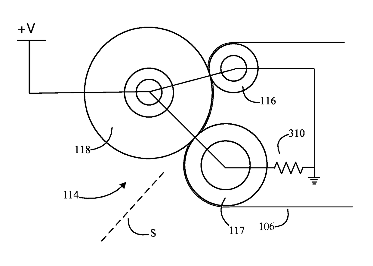
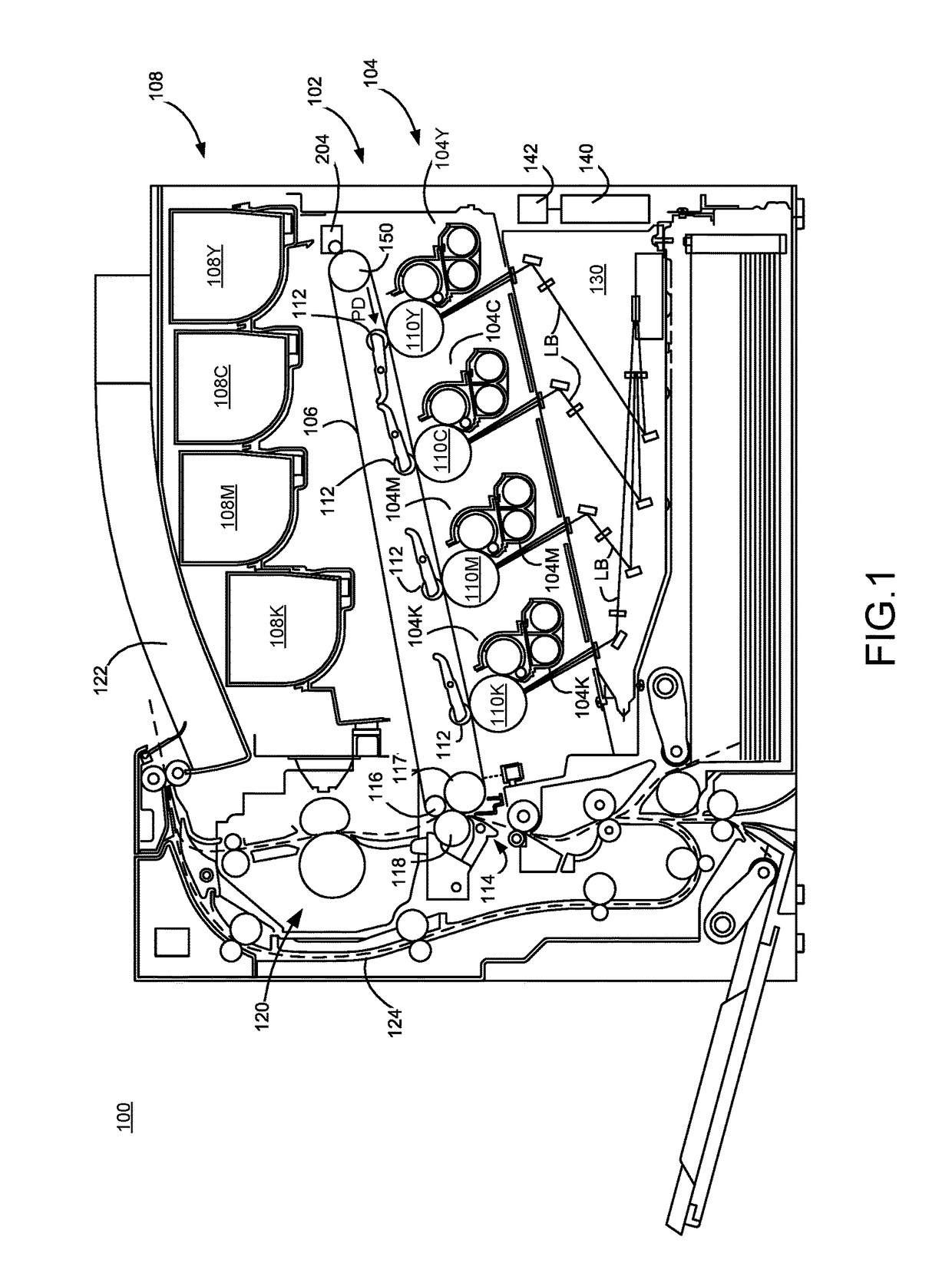
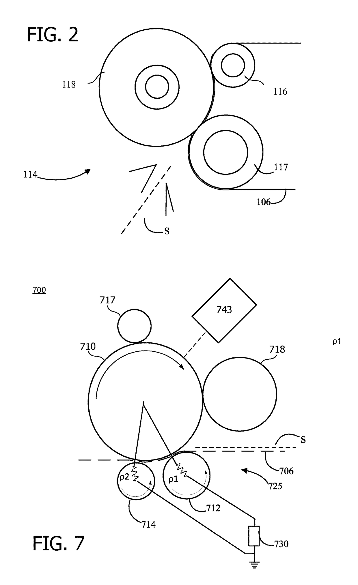
[0011]Example embodiments of the present disclosure overcome shortcomings seen in prior transfer nip designs and thereby satisfy a significant need for an electrophotographic imaging system having a transfer nip whose electric fields can be quickly and easily controlled so as to avoid Paschen breakdown and over-transfer of toner. In one embodiment, the transfer nip includes an intermediate transfer member (ITM) belt forming an endless loop having an inner surface and an outer surface; a transfer roll disposed along the outer surface of the ITM belt; and first and second rolls, with each first roll and second roll being disposed within the ITM belt relative to the transfer roll, the second roll forming a transfer nip with the transfer roll, and the first roll being disposed upstream relative to the second roll in a media feed direction. During a toner transfer operation, the transfer roll is coupled to a predetermined voltage and the first and second rolls are coupled to at least one voltage reference so that an electric field is generated between the transfer roll and the first roll and between the transfer roll and the second roll. The first roll is associated with an electrical characteristic such that the electric field generated between the transfer roll and the first roll is limited during the toner transfer operation relative to the electric field generated between the transfer roll and the second roll. In an example embodiment, the first roll, second roll and the transfer roll form a transfer nip such that during the toner transfer operation, a majority of toner transfers from the ITM belt in the exit nip region by the electric field formed by the transfer roll and the second roll, at least partly due to the electrical characteristic associated with the first roll.

Problems solved by technology

The result is a loss of operating space for second transfer in some environments, such as class-B environments.

Method used


Image

  • Controlled transfer nip for an electrophotographic device and method of using same
  • Controlled transfer nip for an electrophotographic device and method of using same
  • Controlled transfer nip for an electrophotographic device and method of using same

Examples


Embodiment Construction

[0021]It is to be understood that the present disclosure is not limited in its application to the details of construction and the arrangement of components set forth in the following description or illustrated in the drawings. The present disclosure is capable of other embodiments and of being practiced or of being carried out in various ways. Also, it is to be understood that the phraseology and terminology used herein is for the purpose of description and should not be regarded as limiting. The use of “including,”“comprising,” or “having” and variations thereof herein is meant to encompass the items listed thereafter and equivalents thereof as well as additional items. Unless limited otherwise, the terms “connected,”“coupled,” and “mounted,” and variations thereof herein are used broadly and encompass direct and indirect connections, couplings, and positionings. In addition, the terms “connected” and “coupled” and variations thereof are not restricted to physical or mechanical con...


PUM


Abstract

An imaging apparatus, including a transfer roll; and first and second rolls, each first roll and second roll being disposed relative to the transfer roll, the second roll forming a transfer nip with the transfer roll and the first roll being disposed upstream relative to the second roll in a media feed direction. During a toner transfer operation, the transfer roll is coupled to a predetermined voltage and the first and second rolls are coupled to at least one voltage reference so that an electric field is generated between the transfer roll and the first roll and between the transfer roll and the second roll, the first roll being associated with an electrical characteristic such that the electric field generated between the transfer roll and the first roll is limited during the toner transfer operation relative to the electric field generated between the transfer roll and the second roll.

Description

BACKGROUND[0001]1. Field of the Disclosure[0002]The present disclosure relates generally to an image forming apparatus and, more particularly, to a system and method for effectively controlling the shape of the electric field in the transfer nip of the image forming apparatus so as to avoid Paschen breakdown and over-transfer of toner in the transfer nip.[0003]2. Description of the Related Art[0004]This present disclosure concerns the transfer process for electrophotographic printers. It applies to both two step toner transfer and direct-to-paper imaging systems. Specifically it applies to the transfer process, whereby toner is moved from a donating medium, such as a transfer belt, to an accepting medium, such as a sheet of paper.[0005]Transfer is a core process in an electrophotographic printing process. The process starts when a photosensitive roll, such as a photoconductor, is charged and then selectively discharged to create a charge image. The charge image is developed by a dev...

Claims


Application Information

Patent Timeline
Patent Type & Authority Patents(United States)
IPC IPC(8): G03G15/16
CPCG03G15/162G03G15/1605G03G15/1615G03G15/1675
Inventor EMBRY, KERRY L.WHITNEY, JULIE ANN GORDON
Owner LEXMARK INT INC
Why Eureka
Try Eureka