
Two-speed electric drive unit

a technology of electric drive and electric motor, which is applied in the direction of electric propulsion mounting, electric propulsion, transportation and packaging, etc., can solve the problems of difficult and costly integration of electric drive or hybrid drive with downstream reduction gear set and differential gear assembly in motor vehicles, and achieves improved off-road mobility, low cost, and high gear reduction ratio

Active Publication Date: 2017-05-02
DANA AUTOMOTIVE SYST GRP LLC
View PDF29 Cites 23 Cited by
  • Summary
  • Abstract
  • Description
  • Claims
  • Application Information

AI Technical Summary

Benefits of technology

The electric drive unit described in this patent allows for better torque distribution and improved off-road mobility in all-wheel drive vehicles. It also allows for a high gear reduction ratio, which means a small motor and inverter package can be used. This reduces the cost of the vehicle and makes it more efficient.

Problems solved by technology

Hybrid all-wheel drive systems present packaging difficulties for vehicle design.
The integration of an electric drive or a hybrid drive with a downstream reduction gear set and differential gear assembly in a motor vehicle is often difficult and costly due to additional components required for the electric drive and the limited available space.

Method used


Image

  • Two-speed electric drive unit
  • Two-speed electric drive unit
  • Two-speed electric drive unit

Examples


Embodiment Construction

[0012]It is to be understood that the invention may assume various alternative orientations and step sequences, except where expressly specified to the contrary. It is also to be understood that the specific devices and processes illustrated in the attached drawings, and described in the following specification are simply exemplary embodiments of the inventive concepts defined in the appended claims. Hence, specific dimensions, directions or other physical characteristics relating to the embodiments disclosed are not to be considered as limiting, unless the claims expressly state otherwise.

[0013]The invention comprises a two-speed drive unit for an electric motor used in motor vehicles.

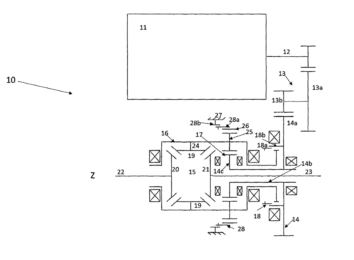
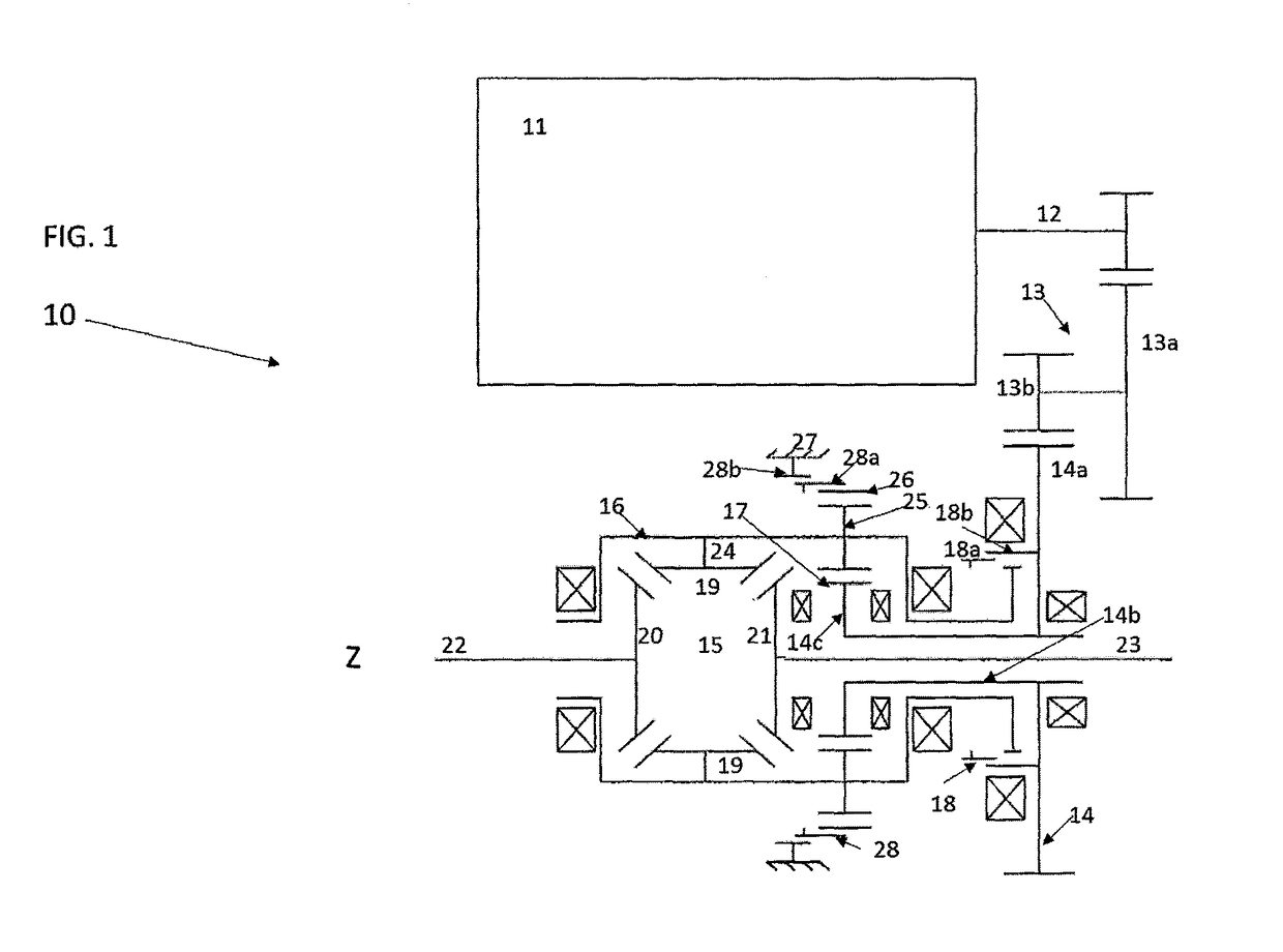
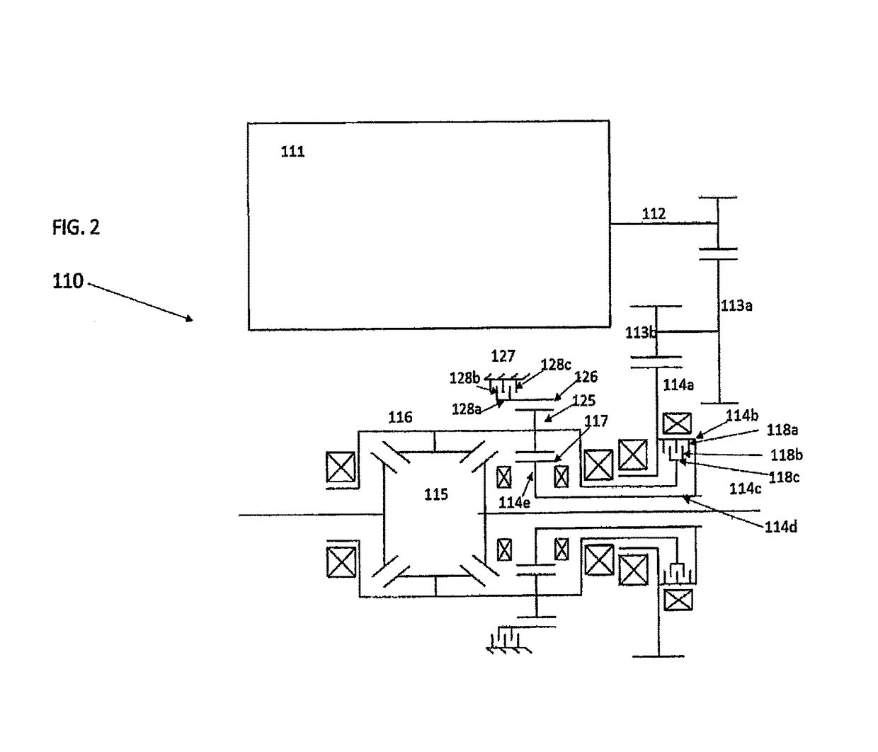
[0014]As shown in FIG. 1, a preferred embodiment of an electric drive unit 10 includes an electric motor 11, an output shaft 12, a reducing gear set 13, a drive input gear 14 and a differential gear arrangement 15. In the preferred embodiment, the electric motor 11 is positioned radially outward from ...


PUM


Abstract

An electric drive unit for a vehicle including an electric motor, a differential housing, a reducing gear set, a drive input gear, a first clutch and a second clutch. The differential housing forms a carrier for a plurality of planetary gears which are in driving engagement with the drive input gear. The drive input gear is in driving engagement with the reducing gear which connected to the electric motor. A ring gear outside the differential housing is in driving engagement with the planetary gears. The first clutch can be engaged to couple the drive input gear to the differential housing resulting in the electric drive unit being placed in a first drive ratio and a second clutch can be engaged to ground the ring gear resulting in the electric drive unit being placed in a second drive ratio.

Description

FIELD OF THE INVENTION[0001]The present invention relates to electric drive systems for motor vehicles. More specifically, the present disclosure relates to a two-speed electric drive unit for electric or hybrid cars.BACKGROUND OF THE INVENTION[0002]Electric drive units typically comprise an electric motor and a reduction drive arranged to reduce the rotational movement produced by the electric motor. The torque is transmitted from the reduction drive to a differential assembly which splits the torque onto two output shafts for driving wheels.[0003]Electric or hybrid vehicles with an electric drive unit have long been known. Hybrid electric vehicles have a structure which combines two power sources, typically an internal combustion engine and an electric motor, to produce lower emissions. Hybrid electric drive units are being developed for use in all-wheel drive vehicles such that the motor and the engine can transmit power to both a front set of driven wheels and rear set of driven...

Claims


Application Information

Patent Timeline
Patent Type & Authority Patents(United States)
IPC IPC(8): F16H48/10F16H37/08B60W30/18B60W10/12B60W10/08B60W10/115
CPCB60W30/18F16H37/0813B60W10/08B60W10/115B60W10/12F16H48/10B60W2510/081B60W2710/1005B60W2710/081B60K1/00B60K2001/001Y02T10/72
Inventor COOPER, KENNETH E.
Owner DANA AUTOMOTIVE SYST GRP LLC
Learn More