Eureka AIR delivers breakthrough ideas for toughest innovation challenges, trusted by R&D personnel around the world.

Liquid crystal slit grating and stereoscopic display device

a stereoscopic display and liquid crystal technology, applied in the field of stereoscopic display, can solve the problems of inability to accurately control the position of a ball spacer, inability to accurately control the effect of the ball so as to accurately control the position of every photo spacer, accurately control the impact of the spacer on light transmittance, and accurately control the crosstalk caused

Active Publication Date: 2017-04-25
BOE TECH GRP CO LTD
View PDF25 Cites 1 Cited by
  • Summary
  • Abstract
  • Description
  • Claims
  • Application Information

AI Technical Summary

Benefits of technology

[0009]The present invention provides a liquid crystal slit grating and a stereoscopic display device. The liquid crystal slit grating according to the present invention can accurately control effect of spacers on light transmittance or accurately control crosstalk caused by spacers. The stereoscopic display device according to the present invention can improve three dimensional effect of the stereoscopic display device during three dimensionally displaying.
[0029]The liquid crystal slit grating provided by the present invention may accurately control the position of every photo spacer by using photo spacers formed through mask, lithography process and the like, and thus can accurately control impact of spacers on light transmittance or accurately control crosstalk caused by spacers. The stereoscopic display device provided by the present invention including the liquid crystal slit grating according to the present invention, and accordingly can improve three dimensional effect of the stereoscopic display device during three dimensionally displaying.

Problems solved by technology

As ball spacers are disposed by way of spraying, a lot of ball spacers are sprayed in opaque stripe area and a lot of ball spacers are sprayed in transparent stripe area at the same time, and the location of a ball spacer cannot be accurately controlled.
Therefore, for liquid crystal slit grating in normally white mode, the formation manner of the ball spacers will cause that the location of each ball spacer cannot be accurately controlled, and further the effect of the ball spacers on light transmittance cannot be accurately controlled.
Therefore, for liquid crystal slit grating in normally black mode, the formation manner of the ball spacers will cause that the locations of ball spacers cannot be accurately controlled, and further crosstalk caused by the ball spacers cannot be accurately controlled.
The above problems exist not only in a TN mode liquid crystal slit grating, but also in a liquid crystal slit grating of other mode, such as a ADSDS mode liquid crystal slit grating.

Method used


Image

  • Liquid crystal slit grating and stereoscopic display device
  • Liquid crystal slit grating and stereoscopic display device
  • Liquid crystal slit grating and stereoscopic display device

Examples


Embodiment Construction

[0045]The embodiments of the present invention will be described clearly and completely in conjunction with the accompanying drawings illustrating the embodiments of the present invention below. However, the described embodiments are illustrative and not restrictive. Based on the teaching of the present invention, modifications and variations can be made to each embodiment by the person skilled in the art in detail and formality, and the present invention is intended to include all these modifications and variations.

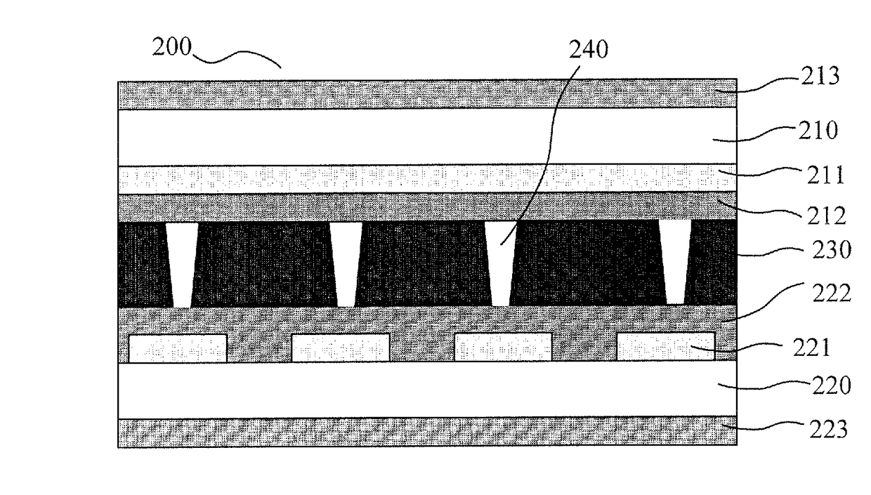
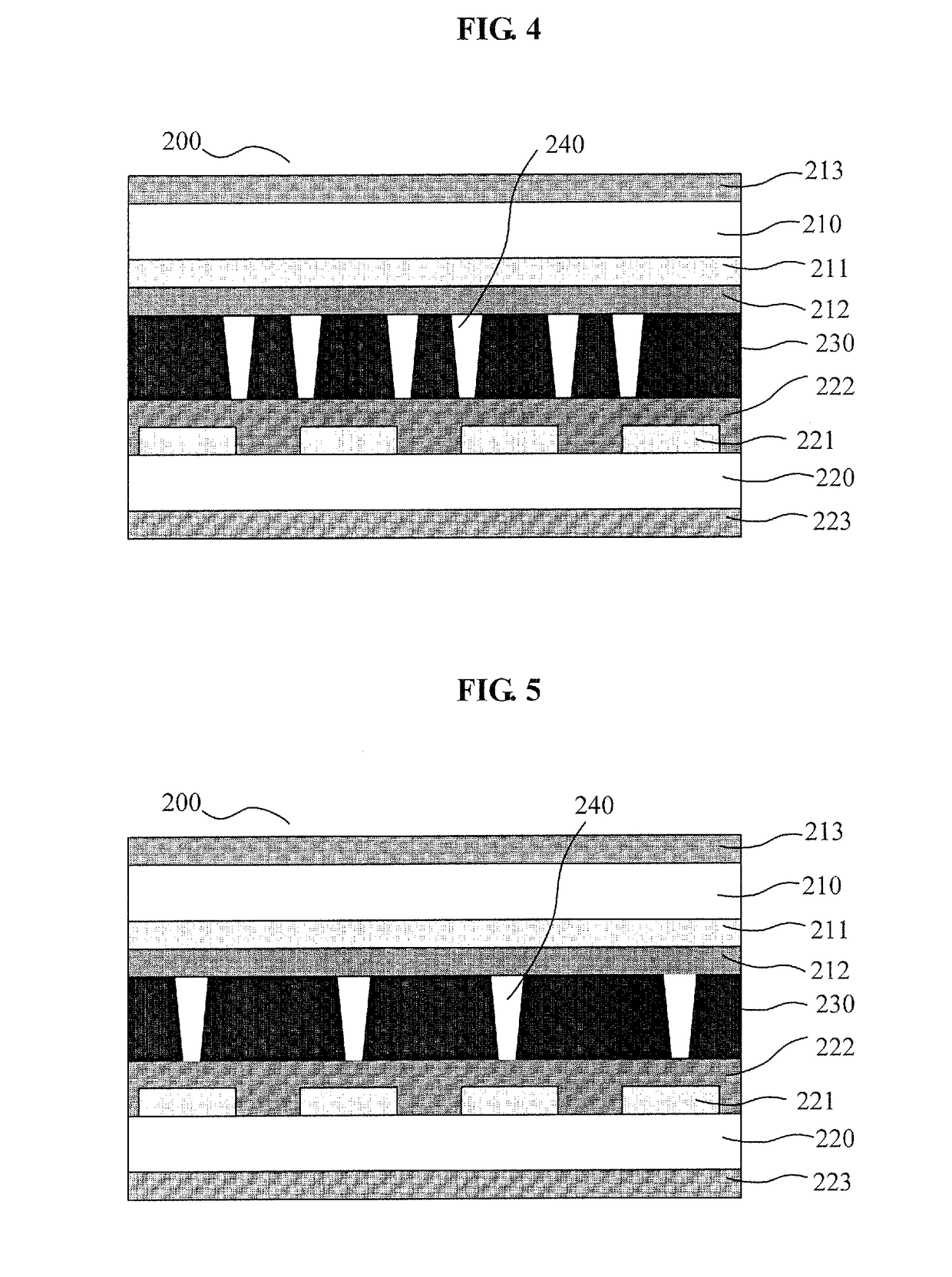
[0046]FIG. 4 is a schematic diagram of liquid crystal slit grating 200 according to an embodiment of the present invention. As shown in FIG. 4, the liquid crystal slit grating 200 may include a first grating substrate and a second grating substrate facing each other, and further include a plurality of photo spacers 240 provided between the first grating substrate and the second grating substrate. Nematic liquid crystal layer 230 with twisted angle of 90 degree may be pro...


PUM

PropertyMeasurementUnit
twisted angleaaaaaaaaaa
areaaaaaaaaaaa
transparentaaaaaaaaaa

Abstract

The present invention discloses a liquid crystal slit grating and a stereoscopic display device, the liquid crystal slit grating includes a first grating substrate and a second grating substrate facing each other, and a plurality of photo spacers supporting between the first grating substrate and the second grating substrate; the stereoscopic display device includes a display panel and said liquid crystal slit grating which is parallel to each other. The liquid crystal slit grating of the present invention provides conditions for accurately controlling effects of the photo spacers on light transmittance or accurately controlling crosstalk caused by the photo spacers. The stereoscopic display device of the present invention provides conditions for improving 3D effect of stereoscopic display device during three dimensionally displaying.

Description

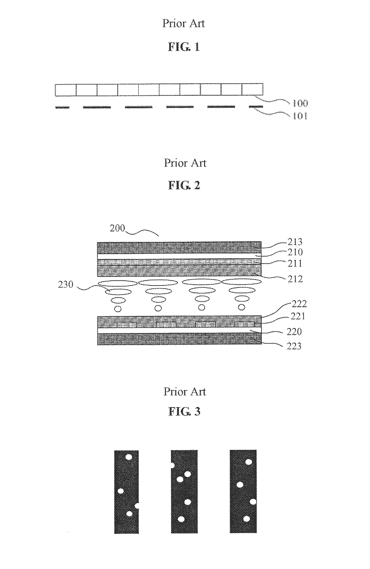
FIELD OF THE INVENTION[0001]The present invention relates to technical field of stereoscopic display, and particularly, to a liquid crystal slit grating and a stereoscopic display device.BACKGROUND OF THE INVENTION[0002]An autostereoscopic display device refers to a display device with which an image with stereoscopic effect can be observed through naked eyes without wearing glasses. A slit grating type autostereoscopic display device can alternately display pixels of a display panel by column as left parallax images and right parallax images, and a grating is provided in front of or behind the display panel in parallel. In a basic structure as shown in FIG. 1, gratings 101 are parallel provided in front of display panel 100. With the shielding effect of the gratings, the left eye and right eye of an observer see left parallax images and right parallax images displayed by pixels on a display panel, respectively, and thus the observer obtains a visual stereoscopic display image. The ...

Claims


Application Information

Patent Timeline
Patent Type & Authority Patents(United States)
IPC IPC(8): G02B27/26G02B27/22G02F1/1339G02B30/25G02B30/31
CPCG02B27/2214G02F1/13394G02B27/26G02B30/25G02B30/31G02B30/27
Inventor WU, YANBING
Owner BOE TECH GRP CO LTD
Why Eureka
Eureka Blog
Learn More