Columnar air moving devices, systems and methods

a technology of moving devices and columns, applied in ventilation systems, lighting and heating apparatus, heating types, etc., can solve the problems of stagnant or dead air in low and high ceiling rooms, affecting the air quality of the room, and reducing the cost of heating and air conditioning. , to achieve the effect of minimal lateral dispersion, minimal rotary component, and minimal lateral dispersion

Active Publication Date: 2017-04-25
AIRIUS IP HLDG
View PDF329 Cites 35 Cited by
  • Summary
  • Abstract
  • Description
  • Claims
  • Application Information

AI Technical Summary

Benefits of technology

The patent describes an air moving device that can create a column of air with minimal dispersion. This device has a rotary impeller with blades and air guide vanes that work together to create a smooth air flow. It can be used to move air in a simple, efficient way, and is especially useful for high-efficiency air conditioning, improving air quality, and circulation. The device is also suitable for flushing air spaces in containers, trailer trucks, and rooms.

Problems solved by technology

Such air temperature stratification is particularly problematic in large spaces with high ceilings such as warehouses, gymnasiums, offices, auditoriums, hangers, commercial buildings, and even residences with cathedral ceilings, and can significantly decrease heating and air conditioning costs.
Further, both low and high ceiling rooms can have stagnant or dead air.
For standard ceiling heights with duct outlets in the ceiling there is a sharp rise in ceiling temperatures when the heat comes on.
Conventional ceiling fans are generally ineffective as an air de-stratification device in relatively high ceiling rooms because the air pushed by conventional ceiling fans is not maintained in a columnar pattern from the ceiling to the floor, and often disperses or diffuses well above the floor.
Such devices, when located away from the walls in an open space in a building, interfere with floorspace use and are not aesthetically pleasing.
When confined to locations only along the walls of an open space, such devices may not effectively circulate air near the center of the open space.
Perkins, however, does not disclose the importance of a specific, relatively small gap between the impeller blades and the stationary vanes, and the device illustrated creates a vortex and turbulence due to a large gap and centrifugal air flow bouncing off the inner walls of the housing between the blades and vanes.

Method used


Image

  • Columnar air moving devices, systems and methods
  • Columnar air moving devices, systems and methods
  • Columnar air moving devices, systems and methods

Examples


Embodiment Construction

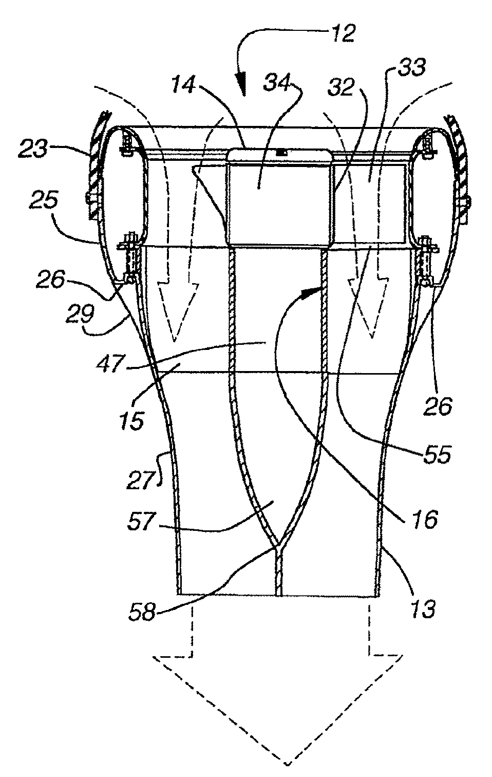
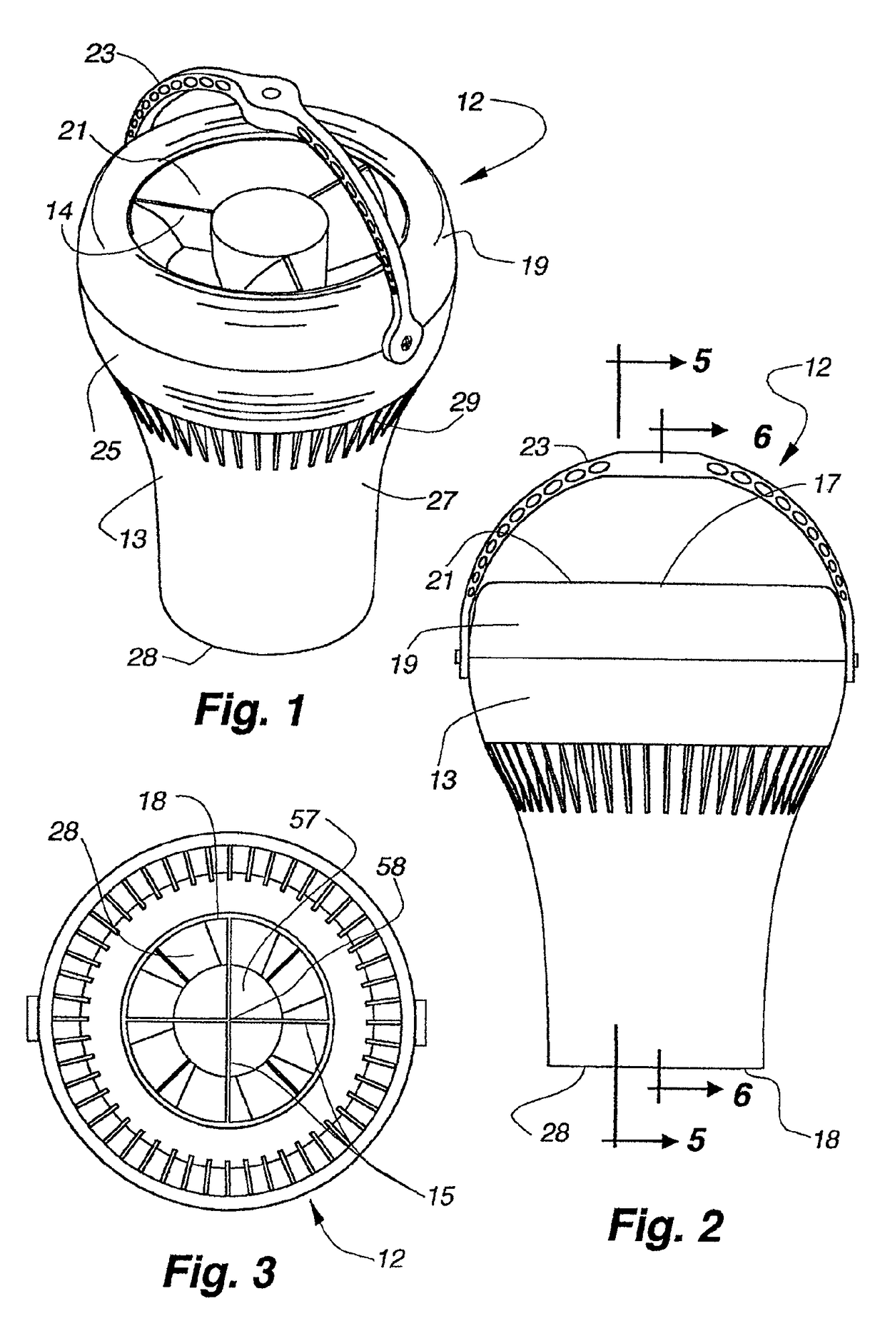
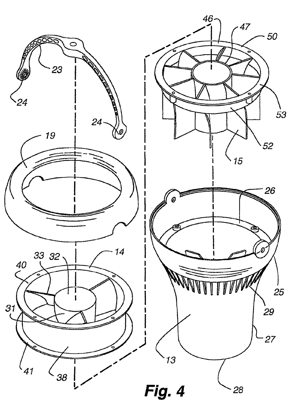
[0037]Referring now to FIGS. 1 to 9, there is shown an air moving device 12 having an elongated outer housing 13, an electric rotary fan 14 in the housing for producing air flow in the housing and a plurality of longitudinally extending, outer radial vanes 15 and an inner housing hub 16 opposite the vanes in the housing downstream of the fan for directing air flow in the housing.

[0038]The housing 13 has a circular cross section, and an open first end 17 and an open second end 18 spaced from the first end 17. In the illustrated embodiment, a detachable, axially outwardly convex cowling 19 forms the first end 17 and provides an air inlet 21 with a diameter slightly smaller than the outer diameter of the cowling 19.

[0039]The housing 13 has a first section 25 extending from the cowling 19 to an interior shelf 26. A generally C shaped hanger 23 mounts at opposite ends 24 to opposite sides of the housing 13 at the upper end of the first section 25, for mounting the air moving device 12 to...


PUM


Abstract

Air moving device includes a housing, an impeller in the housing for generating a downward air flow, and vanes in the housing in close proximity to and a selected distance below the impeller to straighten the air flow. The device produces an air flow that substantially remains in a column over a substantial distance. The method includes producing an air flow that substantially remains in a column over a substantial distance and directing the air flow from the ceiling towards the floor to provide temperature destratification of the air in an enclosed space. The method also includes directing warm air from the ceiling to the floor and storing heat in the floor, apparatus on the floor and ground under the floor. The stored heat is released when the ceiling is cooler than the floor.

Description

CROSS-REFERENCE TO RELATED APPLICATIONS[0001]This application is a continuation of U.S. application Ser. No. 13 / 365,223, filed Feb. 2, 2012, incorporated in its entirety by reference herein, which is a continuation-in-part of U.S. application Ser. No. 12 / 130,909, filed May 30, 2008, incorporated in its entirety by reference herein, which is a continuation of U.S. application Ser. No. 11 / 027,039, filed Dec. 30, 2004 now U.S. Pat. No. 7,381,129, issued Jun. 3, 2008, incorporated in its entirety by reference herein, which claims the benefit under 35 U.S.C. §119(e) to U.S. Provisional Patent Application No. 60 / 553,720 filed Mar. 15, 2004, which is incorporated in its entirety by reference herein. U.S. application Ser. No. 13 / 365,223 also claims the benefit under 35 U.S.C. §119(e) to U.S. Provisional Patent Application No. 61 / 521,270 filed Aug. 8, 2011, which is incorporated in its entirety by reference herein.BACKGROUND OF THE INVENTION[0002]Field of the Invention[0003]The present inven...

Claims


Application Information

Patent Timeline
Patent Type & Authority Patents(United States)
IPC IPC(8): F04D25/08F24F7/007B23P19/00F04D13/06F04D29/52F21V33/00F04D25/12F04D29/54F04D29/60
CPCF04D25/088B23P19/00F04D13/0613F04D25/12F04D29/522F04D29/547F04D29/601F21V33/0096F24F7/007F24F2221/02F24F2221/14F04D19/002F04D29/325F04D29/329F04D29/4226F04D29/542
Inventor AVEDON, RAYMOND B.
Owner AIRIUS IP HLDG
Why Eureka
Try Eureka