
Wind turbine stabilization

a wind turbine and stabilizer technology, applied in the direction of floating buildings, vessel movement reduction by gyroscopes, anchoring arrangements, etc., to achieve the effect of dampening undeired movements, preventing detected tower movements, and short tim

Inactive Publication Date: 2017-04-18
GE RENEWABLE TECH WIND BV
View PDF19 Cites 7 Cited by
  • Summary
  • Abstract
  • Description
  • Claims
  • Application Information

AI Technical Summary

Benefits of technology

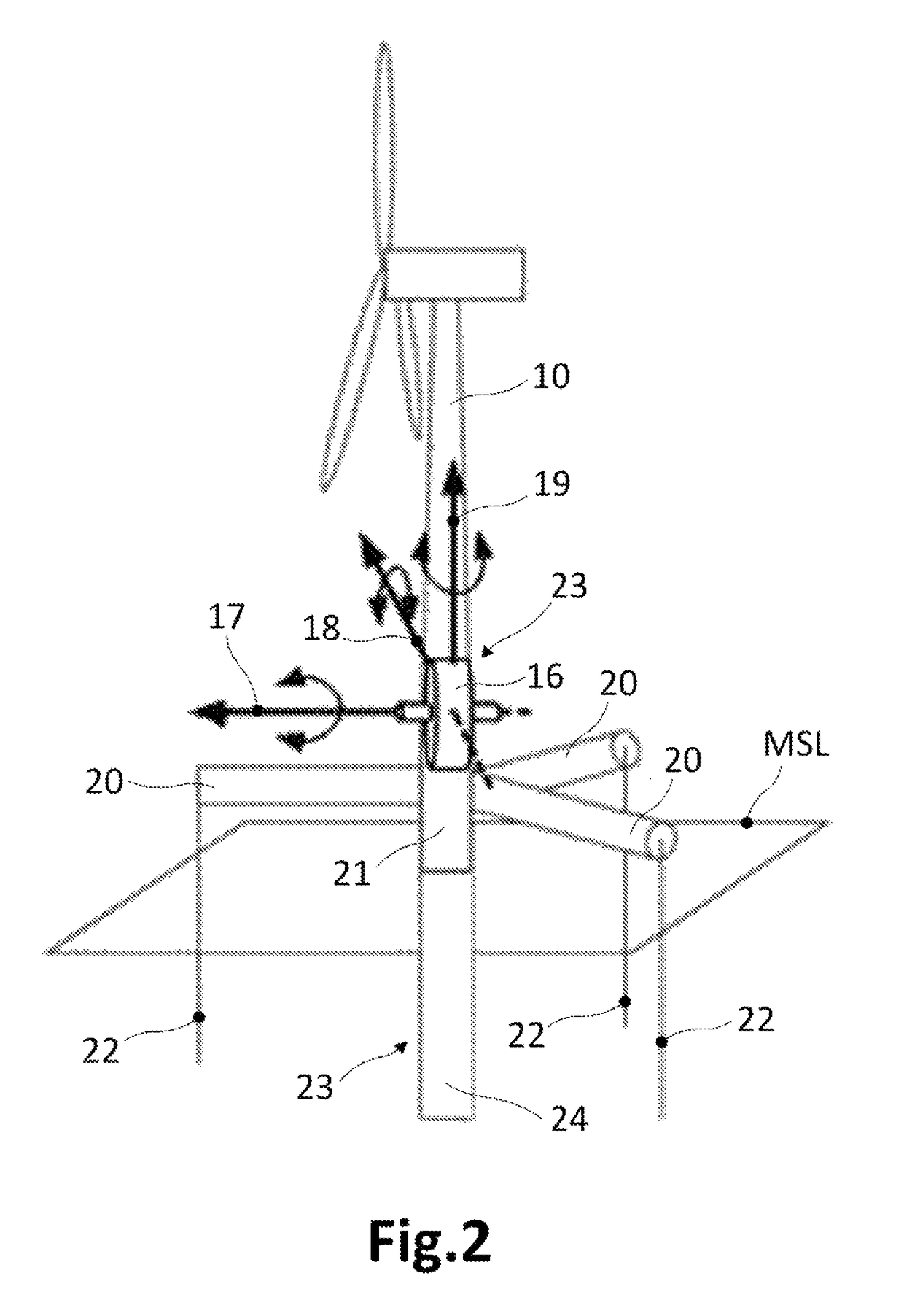
[0011]In a first aspect, the present invention provides a system for stabilizing an offshore horizontal axis wind turbine having a tower. This system comprises at least one sensor for generating sensor signals representing detected movements of the tower, and one or more gyroscopes. Each gyroscope has three mutually perpendicular axes: a spinning axis, an input axis and an output axis, and a flywheel rotatable about the spinning axis. The system further comprises a first gyroscope actuator for each gyroscope, said first gyroscope actuator being arranged with its related gyroscope in such a way that this first gyroscope actuator can apply a torque about the input axis of the gyroscope. The system also comprises a control unit for receiving the sensor signals representing detected movements of the tower, and for providing at least one of the first gyroscope actuators with suitable control signals for said first gyroscope actuator to apply a torque about the related gyroscope input axis, said torque about the input axis producing a torque about the output axis of the same gyroscope that at least partly dampens the detected movements of the tower.
[0012]One of the key points of this system is the use of gyroscopes for dampening undesired movements of an offshore wind turbine. Gyroscopes are very suitable for that goal as they can be attached to any floating rigid body (i.e. an offshore wind turbine) in such a way that the whole structure of said body can jointly move with the whole structure of the gyroscope. Thus, according to the principles of gyroscopic operation, the application of controlled torques about an axis of the gyroscope may produce reaction torques about another axis of the gyroscope, such that the gyroscope can force the body to move conveniently. These controlled torques may be such that these forced movements may at least partly oppose or counteract the undesired movements of the wind turbine.
[0013]Particularly, the stabilizing system of the invention may permit dampening undesired movements in offshore horizontal axis wind turbines by sensing / detecting movements of the tower, and producing suitable control signals depending on the detected movements. These control signals can be sent to the corresponding one or more actuators for them to properly act on the one or more gyroscopes to produce one or more reaction torques (at least partly) dampening the detected movements. This active control of the one or more gyroscopes permits reacting to destabilizing movements in a substantially short time and / or with a more appropriated torque(s) in comparison with e.g. a gyroscope under “free” operation. Further, the proposed stabilizing system may permit a good dampening of yawing movements of the wind turbine by arranging one of the gyroscopes such that suitable reaction torques can be produced about a longitudinal axis of the tower.
[0014]In some embodiments, the system may comprise, for at least one of the gyroscopes, a second gyroscope actuator arranged with said gyroscope in such a way that this second gyroscope actuator can apply a torque about the output axis of the gyroscope. Moreover, the control unit may be adapted to provide the second gyroscope actuator with suitable control signals for said second gyroscope actuator to apply a torque about its related output axis, said torque about the output axis causing a torque about the input axis of the same gyroscope that at least partly dampens the detected movements of the tower. Besides, the control unit may be adapted to alternatively provide the suitable control signals to the first gyroscope actuator or to the second gyroscope actuator related to the same gyroscope, depending on the detected movements of the tower. In these embodiments, the control unit may act on the gyroscope in such a way that alternate reaction torques about the output axis and about the input axis may be produced. Therefore, these embodiments have the advantage of that a single gyroscope may permit dampening two different types of destabilizing movements: rolling and pitching, or rolling and yawing, or pitching and yawing.
[0015]In another aspect, an offshore horizontal axis wind turbine having a tower may comprise a stabilizing system as described hereinbefore. In some of said embodiments, at least one of the gyroscopes of the stabilizing system may be arranged in such a way that one of its three mutually perpendicular axes is substantially parallel to a longitudinal axis of the tower. Preferably, at least one of the gyroscope axes that are substantially parallel to the longitudinal axis of the tower is an input or an output axis. If the control unit acts on the gyroscope in such a way that proper reaction torques about this input / output axis are produced, rotational movements about the longitudinal axis of the tower (yawing movements) may be suitably dampened.
[0018]In a second aspect of the invention, a method is provided for stabilizing the offshore horizontal axis wind turbine of the type described hereinbefore. This method comprises the control unit receiving sensor signals representing detected movements of the tower. The method further comprises the control unit providing at least one of the first gyroscope actuators with suitable control signals for said first gyroscope actuator to apply a torque about the related gyroscope input axis, said torque about the input axis producing a torque about the output axis of the same gyroscope that at least partly dampens the detected movements of the tower.

Problems solved by technology

These controlled torques may be such that these forced movements may at least partly oppose or counteract the undesired movements of the wind turbine.

Method used


Image

  • Wind turbine stabilization
  • Wind turbine stabilization
  • Wind turbine stabilization

Examples


Embodiment Construction

[0028]In the following description, numerous specific details are set forth in order to provide a thorough understanding of the present invention. It will be understood by one skilled in the art however, that the present invention may be practiced without some or all of these specific details. In other instances, well known elements have not been described in detail in order not to unnecessarily obscure the description of the present invention.

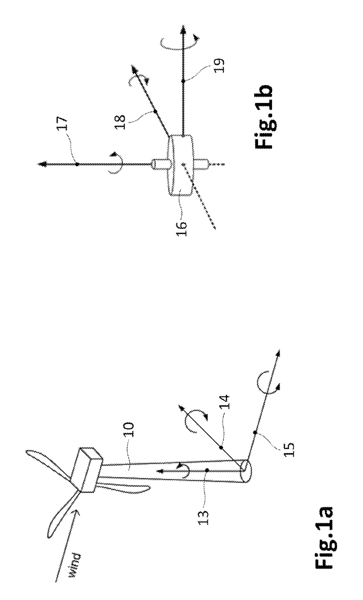
[0029]FIG. 1a is a schematic representation of an offshore horizontal axis wind turbine having a tower 10 and a floating platform (not shown) supporting the tower 10. This figure also shows the main reference axes 13, 14, 15 on a reference frame placed at a bottom region of the tower 10 of the wind turbine. A first of said axes is commonly called yaw axis 13 which substantially coincides with a longitudinal axis of the tower 10. A second of said axes is the pitch axis 14, and a third axis is the roll axis 15 which is aligned with the wind dire...


PUM


Abstract

System for stabilizing an offshore horizontal axis wind turbine having a tower, the system comprising sensors for generating signals representing detected movements of the tower, and gyroscopes. Each gyroscope has a spinning axis, an input axis and an output axis, and a flywheel rotatable about the spinning axis. The system further comprises an actuator for each gyroscope, said actuator being arranged with its related gyroscope in such a way that this actuator can apply a torque about the input axis of the gyroscope. The system also comprises a control unit for receiving the signals representing detected movements of the tower, and for providing the actuator with suitable control signals for said actuator to apply a torque about the related gyroscope input axis, said torque about the input axis producing a torque about the output axis of the same gyroscope that at least partly dampens the detected movements of the tower.

Description

[0001]This application claims the benefit of European Patent Application EP 12382274.4 filed 10 Jul. 2012 and U.S. Provisional Patent Application Ser. No. 61 / 699,113 filed 10 Sep. 2012, the disclosures of which are hereby incorporated by reference in their entirety for all purposes.[0002]The present invention relates to a system for stabilizing an offshore horizontal axis wind turbine having a tower, and to a method suitable to be performed by such a stabilizing system.BACKGROUND ART[0003]Offshore wind turbines are being developed that instead of resting on fixed-bottom support structures have a floating support structure.[0004]Several configurations have been proposed for the floating or buoyancy structures: many of these employ floater elements in the form of hollow floater tanks that in use are arranged substantially below the mean sea level and provide a buoyancy force to support the wind turbine. Ballasts in the floater and / or mooring lines anchored to the seabed are provided f...

Claims


Application Information

Patent Timeline
Patent Type & Authority Patents(United States)
IPC IPC(8): F03D13/20B63B21/50F03D80/80F03D9/12F03D7/06F03D7/02G01C19/02F03D13/25B63B39/04B63B35/44
CPCF03D7/06B63B21/502F03D7/0296F03D9/12F03D13/22F03D13/25F03D80/88G01C19/02B63B39/04B63B2021/505B63B2035/446F05B2240/93F05B2240/95F05B2260/964F05B2270/334Y02E10/723Y02E10/727Y02E60/16Y10T74/1229Y02E10/72Y02E10/74Y02E70/30
Inventor PINEDA AMO, ISAAC
Owner GE RENEWABLE TECH WIND BV
Learn More