
Display driver, electro-optical device, and electronic device

a technology of electrooptical devices and drivers, applied in static indicating devices, cathode-ray tube indicators, instruments, etc., can solve problems such as display flicker and the like, and may arise from frequent switching of electronic volume values, so as to suppress image quality deterioration

Active Publication Date: 2017-04-11
SEIKO EPSON CORP
View PDF11 Cites 1 Cited by
  • Summary
  • Abstract
  • Description
  • Claims
  • Application Information

AI Technical Summary

Benefits of technology

This patent describes a display driver or electro-optical device that can prevent image quality degradation and flickering when switching electronic volume values. The driver uses a temperature sensor to detect temperature, and based on this data, adjusts the drive power supply voltage to prevent such issues. The driver can output multiple interpolated electronic volume values during this adjustment period, further reducing image quality degradation and flickering. Additionally, the driver can simplify circuit design and appropriately determine the temperature range. Overall, this technology ensures a better user experience when using electronic devices.

Problems solved by technology

Also, in the case where the temperature is unstable near the boundary at which the electronic volume value is switched, problems such as frequent switching of the electronic volume value, display flicker and the like may arise.

Method used


Image

  • Display driver, electro-optical device, and electronic device
  • Display driver, electro-optical device, and electronic device
  • Display driver, electro-optical device, and electronic device

Examples


Embodiment Construction

[0045]Hereinafter, preferred embodiments of the invention will be described in detail. Note that the embodiments that will be described below are not intended to unduly limit the contents of the invention as defined in the claims, and not all of the configurations that will be described in the embodiments are essential to means for solving the problems addressed by the invention.

1. Display Driver, Electro-Optical Device

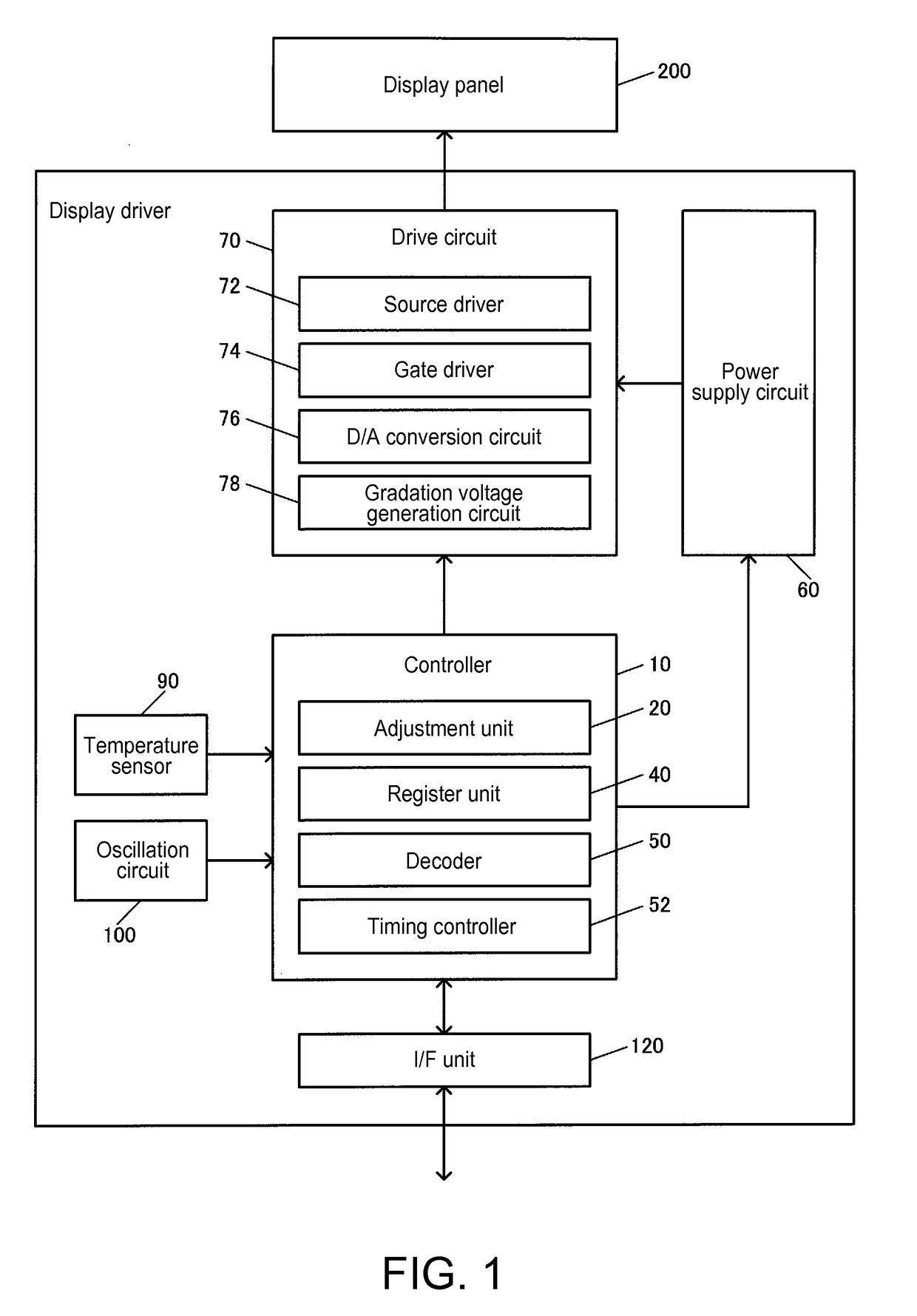
[0046]Exemplary configurations of a display driver of the present embodiment and an electro-optical device that includes this display driver are shown in FIG. 1. The display driver drives a display panel 200, and the display panel 200 displays an image when driven by the display driver. The electro-optical device includes this display driver and the display panel 200 (electro-optical panel). Exemplary electro-optical devices include in-vehicle display units (driver assistance displays, instrument panel displays, car navigation displays, etc.), and display units that a...


PUM


Abstract

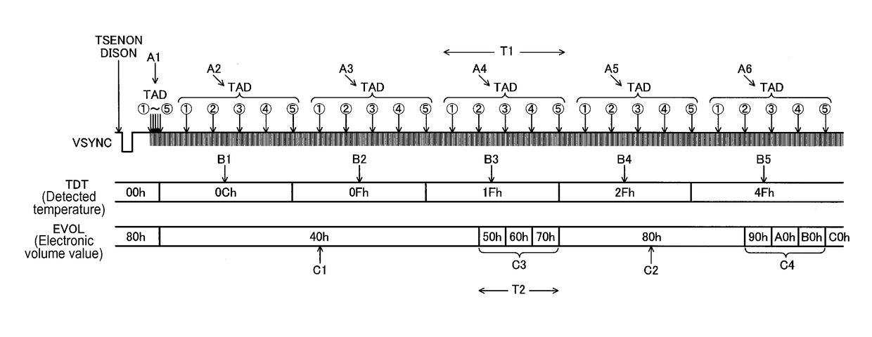
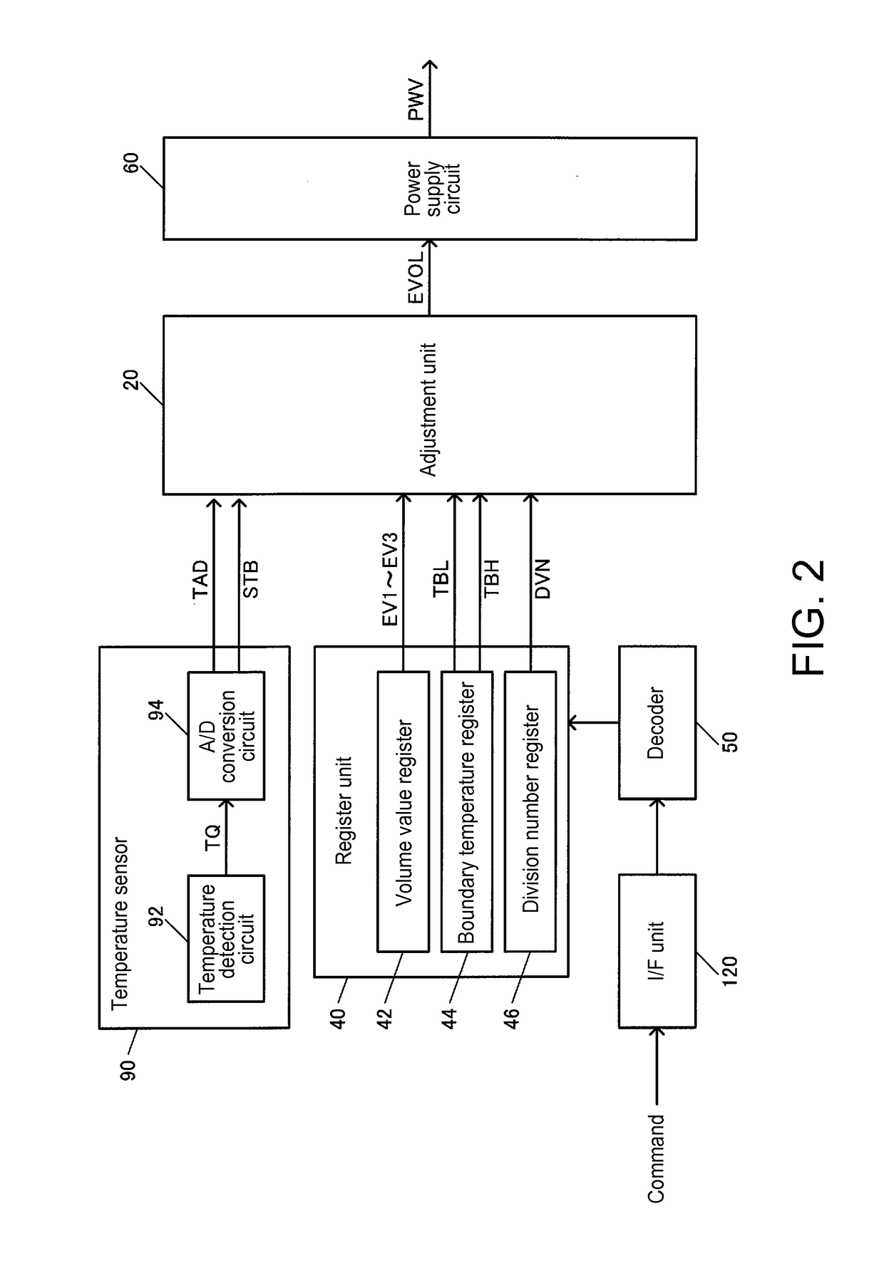
A display driver includes an adjustment unit 20 that outputs an electronic volume value based on a detected temperature derived using a temperature sensor 90, a power supply circuit 60 that supplies a drive power supply voltage based on the electronic volume value, and a drive circuit that drives a display panel based on the drive power supply voltage. The adjustment unit 20 outputs a first electronic volume value that sets the drive power supply voltage to a first voltage, in the case where the detected temperature belongs to a first temperature range, outputs a second electronic volume value that sets the drive power supply voltage to a second voltage, in the case where the detected temperature belongs to a second temperature range, and an interpolated electronic volume value that sets the drive power supply voltage to an interpolated voltage that is between the first voltage and the second voltage, in the case where the temperature range to which the detected temperature belongs switches from the first temperature range to the second temperature range.

Description

BACKGROUND[0001]1. Technical Field[0002]The present invention relates to a display driver, an electro-optical device, an electronic device, and the like.[0003]2. Related Art[0004]Display drivers that drive display panels such as LCD panels are conventionally known. Such display drivers are provided with an electronic volume that adjusts the drive power supply voltage of the display panel, and a temperature sensor that detects the environmental temperature. These display drivers adjust an electronic volume value based on the temperature detected by the temperature sensor, and set the drive power supply voltage to a voltage that depends on the environmental temperature.[0005]Taking an LCD panel as an example, the transmittance of liquid crystal changes at different environmental temperatures, and thus even if the LCD panel is driven at the same drive power supply voltage, the hue of the display image will change. Such changes in the hue can be suppressed by setting the drive power sup...

Claims


Application Information

Patent Timeline
Patent Type & Authority Patents(United States)
IPC IPC(8): G09G5/10G09G3/36
CPCG09G3/3696G09G2320/041G09G2320/0673G09G2330/02
Inventor KOBAYASHI, HIRONORI
Owner SEIKO EPSON CORP
Learn More