
Systems and methods for reducing audio distortion during playback of phonograph records using multiple tonearm geometries

a technology of phonograph records and geometries, applied in the field of analog music conversion, can solve problems such as exceedingly expensive implementation, and achieve the effects of less unwanted ringing, more accurate transcription, and increased accuracy

Inactive Publication Date: 2017-03-28
HOARTY W LEO
View PDF12 Cites 1 Cited by
  • Summary
  • Abstract
  • Description
  • Claims
  • Application Information

AI Technical Summary

Benefits of technology

[0065]It should be understood that an advantage of the invention of using mechanical position means such as the computer controlled positioning mechanism of FIGS. 19 and 20 in conjunction with the optical position recognition system of FIG. 18 is to provide optimal playback quality by abstaining from employing any additional friction inducing sensory mechanisms to detect the tonearm positions both for entry into the respective playback area as well as to detect the point at which the tonearms are to be withdrawn. In prior phonograph playback systems that employ automated tonearm lowering and raising, mechanical means of sensing the tonearm position are employed causing non-uniform pressure on the tonearm and adversely affection playback audio quality.
[0066]Each phonograph cartridge of the invention is connected to an amplification means 1503a and 1503b, which is then connected to respective analog-to-digital converter (ADC) 1504a and 1504b. The digital audio output of the ADC is then captured and stored by the digital audio recording subsystem 1506 which then tags (identifies) and stores the resultant recordings. FIG. 15a depicts an alternative embodiment where the system of the invention employs only one analog-to-digital converter 1524 made possible by the addition of an analog signal switch 1526 which is controlled by the Recording System Controller 1525 to select one at a time of the plurality of input signals from each respective tonearm. In this example, the system selects from one of two tonearm assemblies, 1523a and 1523b. The system of the invention then records sequentially the output of each of the plurality of tonearms for further processing.
[0067]The next stage of processing is the Digital Audio Noise Reduction System 1507 which analyses the recorded audio to remove clicks and pops from the audio by digital signal processing. This is followed by the Digital Audio Stitching System 1508 which uses the splice point data supplied by RSC and then determines the precise byte aligned splice point to join two files. The process is repeated for each recorded sector resulting in one file representing the recorded digital audio of the respective side of the audio record. FIG. 21 illustrated two sample audio segments of overlapping sections of a phonograph recording. The audio signal 2101 depicts the end of the recording of the outer tonearm such as the area of playback 203 of FIG. 2. The audio signal 2102 depicts the overlapping recorded area of the inner tonearm of playback area 204 of FIG. 2. By means of an auto-correlation signal processing algorithm, the overlapping areas of 2101 and 2102 are precisely aligned even though each signal was derived from a separate tonearm. If examined closely, each overlapping area would be digitally converted with differing information due to random noise of the system as well as such factors as differing dirt accumulated on each respective playback stylus. However, the mathematical means of auto-correlation will average out such stochastic differences rending a virtually perfect alignment of the two recordings such that an advantageous splice point may be found for joining the two segments as shown at 2104 of FIG. 21.
[0068]The resulting file is then stored in data storage 1509 and can also be played back in near real time via digital-to-analog converter 1510 or sent over a local area network 1511 to another system. For the purposes of immediate playback, the system of the invention can begin playing back the recorded audio from the first tonearm of the outer-most sector. The second and, if present, additional tonearms also record simultaneously. The second and possible additional sectors will provide enough recorded information to allow the system to detect the start point of each recording and prepare to byte-accurately splice said start point of the second recorded section to the end of the recorded first section. By the end of the first recording section, the remaining section(s) will have also completed or nearly completed. In the presence of more than two sections, all sections will have typically concluded recording before the second section completes playback. Hence, all subsequent recorded sections, if present, are simply digitally spliced to the end of the respective previous section to form a complete recording of the selected side of the record.
[0069]An improvement to the apparatus of the invention would be the addition of a robotic arm to place the record on the turntable from a record storage shelf means. The robotic arm could also be employed to flip the record to its opposite side for the recording of said side and then replace said record back on the record storage shelf and another record would be selected and placed on the turntable analogous to the jukebox mechanisms popular from the 1940's to the 1960's.
[0070]A further improvement of the invention is the process of rotating the turntable platter at one-half speed to playback the phonograph record at half the frequency of the original recording. By means of example, a piano note played on the major scale of middle A of 440 hertz would sound one octave lower at A 220 Hertz. The advantage of this half=speed playback would be to obtain a more accurate transcription of the phonograph record as the playback stylus is moving at one-half the linear velocity of normal playback and hence tracing the mechanical undulations of the recorded surface with additional accuracy. This additional accuracy results from less unwanted ringing of the cantilever to which the playback stylus is attached as well as to greater accuracy of the playback stylus following the impressions on the groove wall of the audio information. The system of the invention would apply an addition processing step of frequency doubling by means of digital up-conversion to restore the audio signal to its original frequency range as would be heard at normal playback speeds. The result of the process using the previous example would be the piano note of the example sounding at A 220 hertz would post processing then sound at note A 440 hertz as intended by the recording. Frequency doubling may also be referred to as up-conversion.

Problems solved by technology

Called a “linear tonearm,” such solutions have been proposed for decades, but have proven to be exceedingly expensive to implement while at the same time introducing their own sources of distortion and noise in terms of side-loading forces on the stylus in the groove and noise from the shuttle mechanism utilized to carry the arm and cartridge, among other problems.

Method used


Image

  • Systems and methods for reducing audio distortion during playback of phonograph records using multiple tonearm geometries
  • Systems and methods for reducing audio distortion during playback of phonograph records using multiple tonearm geometries
  • Systems and methods for reducing audio distortion during playback of phonograph records using multiple tonearm geometries

Examples


Embodiment Construction

[0055]As audio recording, storage and playback systems evolved over the years, subtle noise and distortion artifacts secondary to the technologies then available became more and more detectable to certain classes of listeners. One of the most difficult of these issues to address has been the artifacts inherent in the conflict between the way audio information is recorded to analog audio disks, and the way it is then played back.

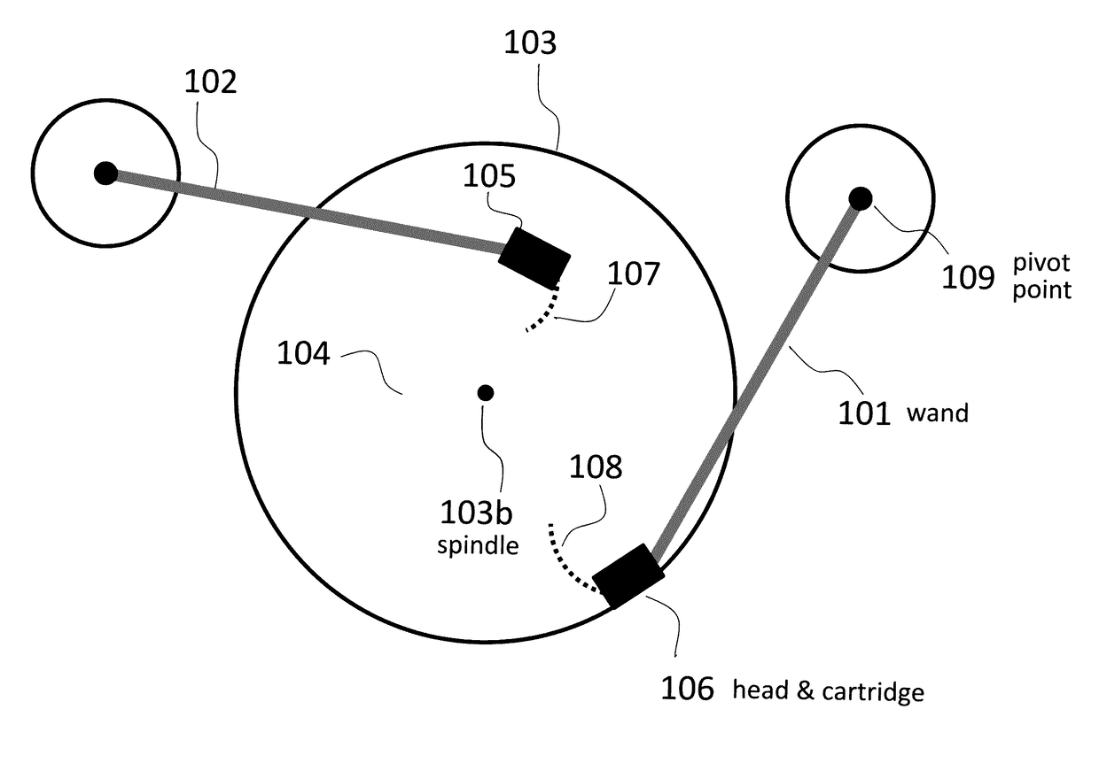
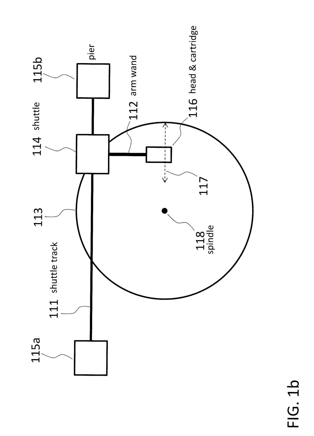
[0056]Vinyl phonograph disks are pressed from molds of a master disk that is cut by a mechanical lathe device; an example of which is shown in FIG. 24. The cutting head is driven by a worm drive across the surface of the disk, passing along a straight radial path from the outermost to the innermost groove as diagramed in FIG. 1b. A problem with playback tracking accuracy arises from the traditional pivoting phonograph tonearm that has been in use in one form or another for almost a century. As the stylus follows the groove, the tonearm pivots causing the styl...


PUM

PropertyMeasurementUnit
distanceaaaaaaaaaa
distanceaaaaaaaaaa
distanceaaaaaaaaaa

Abstract

Systems and methods are disclosed relating to electro-mechanical devices and related computer control and audio processing systems intended to optimize playback fidelity of phonograph records. Said recordings are manufactured by a process that employs a cutting head assembly driven in a straight path from the outer to the inner-most radius of the recordable surface. However, most record turntables device that are used to play back phonograph records rely on a stylus transducer attached to the end of a pivoting arm. Instead of the linear path followed by the original cutting head, said tonearm traces an arc across the surface of the recorded disk resulting in playback distortion proportional to error in alignment of said stylus relative to the tangent of the groove. This invention addresses this deficiency and produces an optimal audio quality of playback of phonograph records.

Description

PRIORITY CLAIM[0001]This application claims the benefit of U.S. Provisional Patent Application No. 62 / 074,076, entitled “SYSTEMS AND METHODS FOR REDUCING AUDIO DISTORTION DURING PLAYBACK OF PHONOGRAPH RECORDS USING MULTIPLE TONEARM GEOMETRIES,” filed Nov. 2, 2014, naming W. Leo Hoarty as the inventor. The foregoing application(s) are either currently or are applications of which the instant or a currently application is entitled to the benefit of the filing date.FIELD OF THE INVENTION[0002]This invention relates generally to the conversion of analog music stored on phonograph records to high-resolution digital files. More specifically, the invention involves a method of employing a plurality of tonearms and phonograph cartridges in association with a single phonograph playback device; with each such tonearm and cartridge pair optimally aligned for some specific subset of the recorded area of the phonograph record in a manner that minimizes the tracking error-induced audio distortion...

Claims


Application Information

Patent Timeline
Patent Type & Authority Patents(United States)
IPC IPC(8): H04B1/20G11B11/20G11B20/02G11B27/026H04H60/04G11B27/028G11B19/00G11B27/034
CPCG11B11/20G11B20/02G11B19/00G11B27/026G11B27/028G11B27/034H04H60/04G11B3/34G11B3/38
Inventor HOARTY, W. LEO
Owner HOARTY W LEO
Learn More