Light source device using monochromatic light to excite stationary phosphor layers
a light source and stationary phosphor technology, applied in the direction of projection devices, lighting and heating apparatus, instruments, etc., can solve the problems of inability to produce small green laser emitting elements with high output, complex cooling mechanism, etc., and achieve the effect of reducing emission periods and improving controllability of the amount of emitted light of each color
- Summary
- Abstract
- Description
- Claims
- Application Information
AI Technical Summary
Benefits of technology
Problems solved by technology
Method used
Image
Examples
first embodiment
[0035]1>
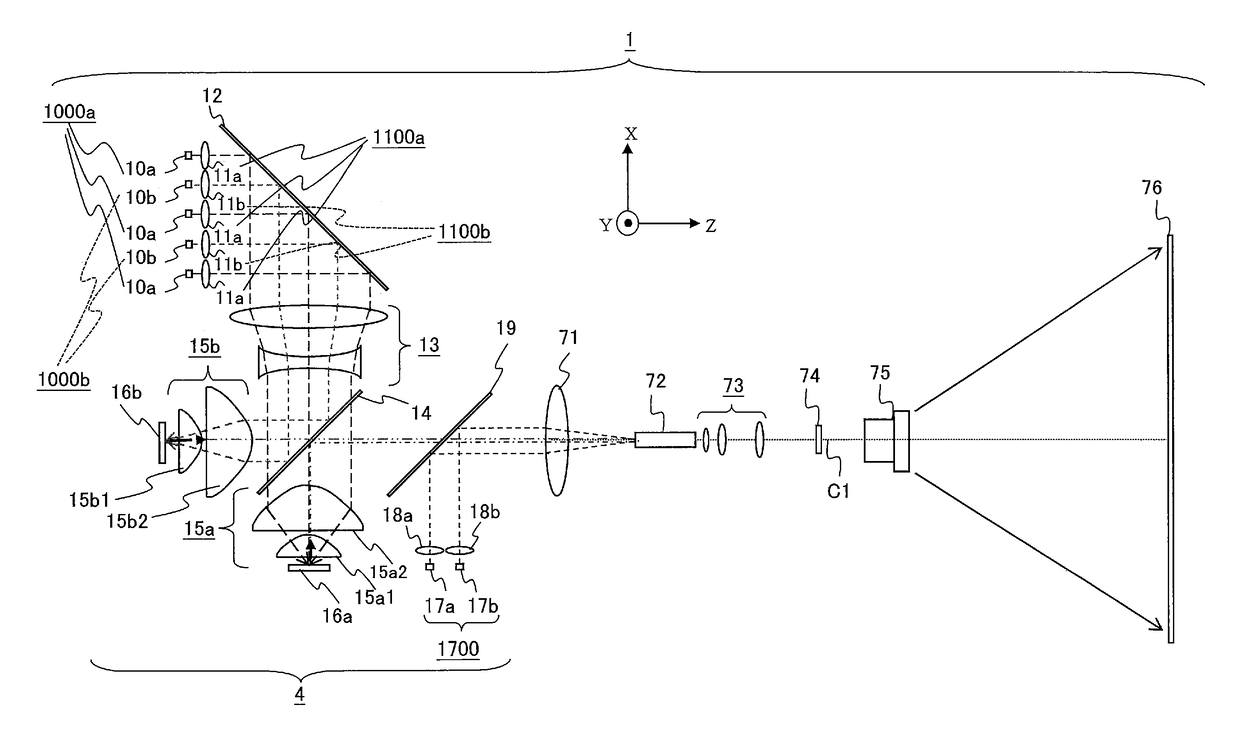
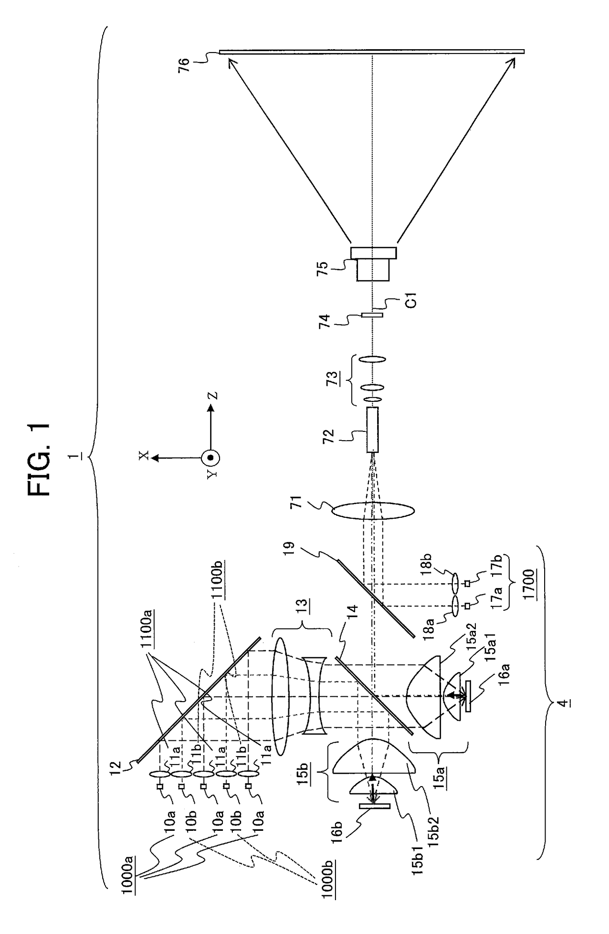
[0036]FIG. 1 is a diagram schematically illustrating a configuration of a projection display device 1 including a light source device 4 according to a first embodiment of the invention. To simplify the description, FIG. 1 shows an orthogonal XYZ coordinate system. The X-axis direction is the vertical direction in FIG. 1. The down-to-up direction in FIG. 1 is the positive X-axis direction; the up-to-down direction is the negative X-axis direction. A lens group 13, a light reflecting element 12, first collimating lenses 11a, second collimating lenses 11b, first monochromatic light sources 10a, and second monochromatic light sources 10b are disposed on the positive X-axis side of a polarization selection and wavelength selection element 14. The Y-axis direction is the direction perpendicular to the drawing sheet on which FIG. 1 is depicted. The positive Y-axis direction is the direction from the reverse side (back side) to the front side of the drawing sheet; the negative Y-axi...
second embodiment
[0103]FIG. 7 is a diagram schematically illustrating a configuration of a projection display device 2 including a light source device 5 according to a second embodiment of the invention. To simplify the description, FIG. 7 shows an orthogonal XYZ coordinate system. The X-axis direction is the vertical direction in FIG. 7. The down-to-up direction in FIG. 7 is the positive X-axis direction; the up-to-down direction is the negative X-axis direction. A lens group 23, a polarization selection element 22, first collimating lenses 21a, second collimating lenses 21b, first monochromatic light sources 20a, and second monochromatic light sources 20b are disposed on the positive X-axis side of a polarization selection and wavelength selection element 24. The Y-axis direction is the direction perpendicular to the drawing sheet on which FIG. 7 is depicted. The positive Y-axis direction is the direction from the reverse side (back side) to the front side of the drawing sheet; the negative Y-axis...
third embodiment
[0120]FIG. 9 is a diagram schematically illustrating a configuration of a projection display device 3 including a light source device 6 according to a third embodiment. To simplify the description, FIG. 9 shows an orthogonal XYZ coordinate system. The X-axis direction is the vertical direction in FIG. 9. The down-to-up direction in FIG. 9 is the positive X-axis direction; the up-to-down direction is the negative X-axis direction. A lens group 33, a light reflecting element 32, first collimating lenses 31a, second collimating lenses 31b, first monochromatic light sources 30a, and second monochromatic light sources 30b are disposed on the positive X-axis side of a polarization selection and wavelength selection element 34. The Y-axis direction is the direction perpendicular to the drawing sheet on which FIG. 9 is depicted. The positive Y-axis direction is the direction from the reverse side (back side) to the front side of the drawing sheet; the negative Y-axis direction is the direct...
PUM
 Abstract
Description
Claims
Application Information
 - R&D
- Intellectual Property
- Life Sciences
- Materials
- Tech Scout
- Unparalleled Data Quality
- Higher Quality Content
- 60% Fewer Hallucinations
Browse by: Latest US Patents, China's latest patents, Technical Efficacy Thesaurus, Application Domain, Technology Topic, Popular Technical Reports.
© 2025 PatSnap. All rights reserved.Legal|Privacy policy|Modern Slavery Act Transparency Statement|Sitemap|About US| Contact US: help@patsnap.com


