
Watercraft

a watercraft and water technology, applied in the field of watercraft, can solve the problems of slow acceleration of watercraft and execution of maximum speed limit control, and achieve the effect of more accurate achievemen

Active Publication Date: 2017-03-21
YAMAHA MOTOR CO LTD
View PDF3 Cites 0 Cited by
  • Summary
  • Abstract
  • Description
  • Claims
  • Application Information

AI Technical Summary

Benefits of technology

[0007]In view of the problems described above, preferred embodiments of the present invention provide a watercraft that accurately determines whether to execute a maximum speed limiting control.
[0009]With the watercraft according to a preferred embodiment of the present invention, the control section executes the maximum speed limiting control when both the prescribed execution condition and the condition that the filtered engine rotational speed is larger than a prescribed rotational speed threshold value are satisfied. Consequently, it is possible to avoid a situation in which the maximum speed limiting control is executed while the engine rotational speed is large but the watercraft is not cruising on water. As a result, the determination of whether to execute the maximum speed limiting control can be accomplished more accurately.
[0010]The reason that the engine rotational speed detected by the engine rotational speed sensor is not used as is and, instead, a filtered engine rotational speed is preferably used will now be explained. A change in the engine rotational speed does not necessarily correspond to an immediate change in watercraft speed. For example, if the watercraft starts rapidly into motion from a state in which the speed is 0, then the engine rotational speed will increase immediately but the watercraft speed will increase gradually and later than the engine rotational speed. Thus, if the engine rotational speed detected by the engine rotational speed sensor were used as is for the determination, then the maximum speed limiting control would be executed even though the watercraft speed has not increased sufficiently and the acceleration of the watercraft would be slow when rapidly starting the watercraft into motion. Therefore, by using a filtered engine rotational speed instead of using the detected engine rotational speed as is, the determination of whether to execute the maximum speed limiting control can be accomplished accurately.

Problems solved by technology

Thus, if the engine rotational speed detected by the engine rotational speed sensor were used as is for the determination, then the maximum speed limiting control would be executed even though the watercraft speed has not increased sufficiently and the acceleration of the watercraft would be slow when rapidly starting the watercraft into motion.

Method used


Image

  • Watercraft
  • Watercraft
  • Watercraft

Examples


Embodiment Construction

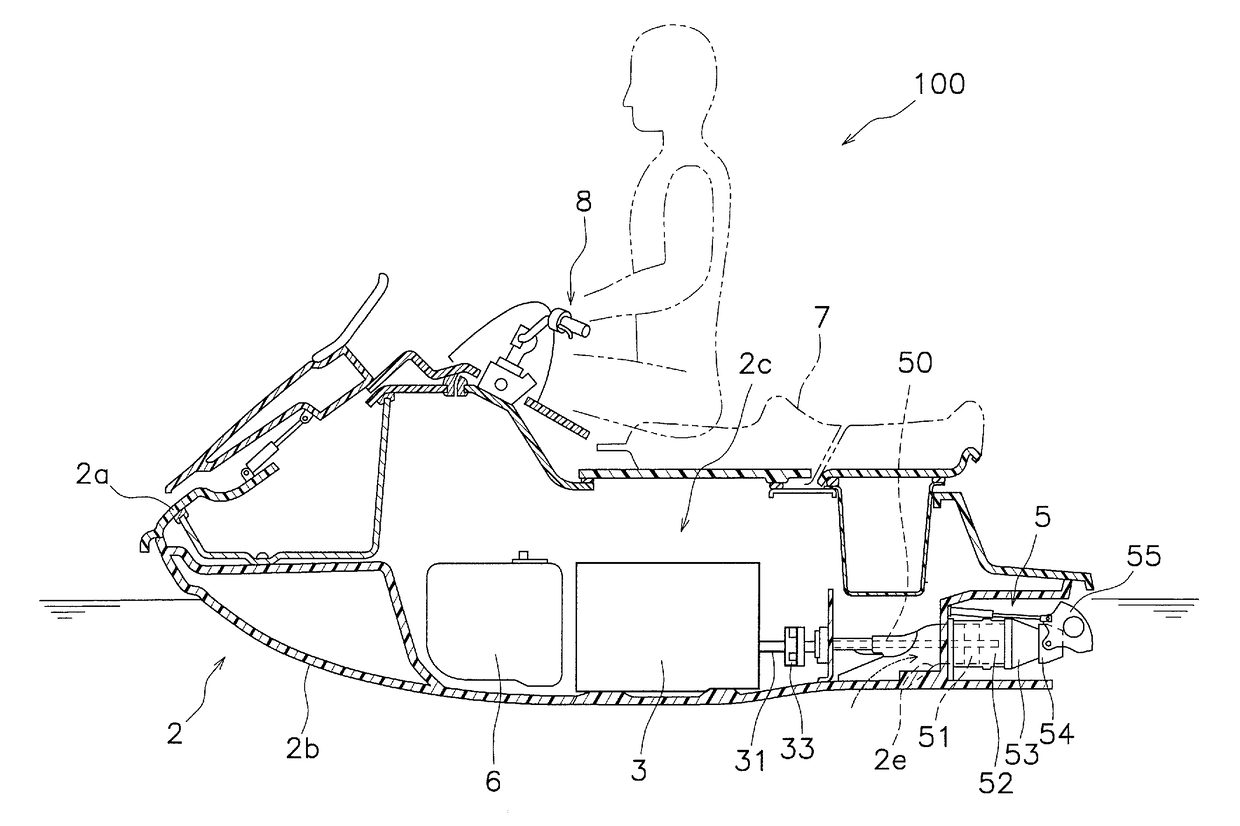
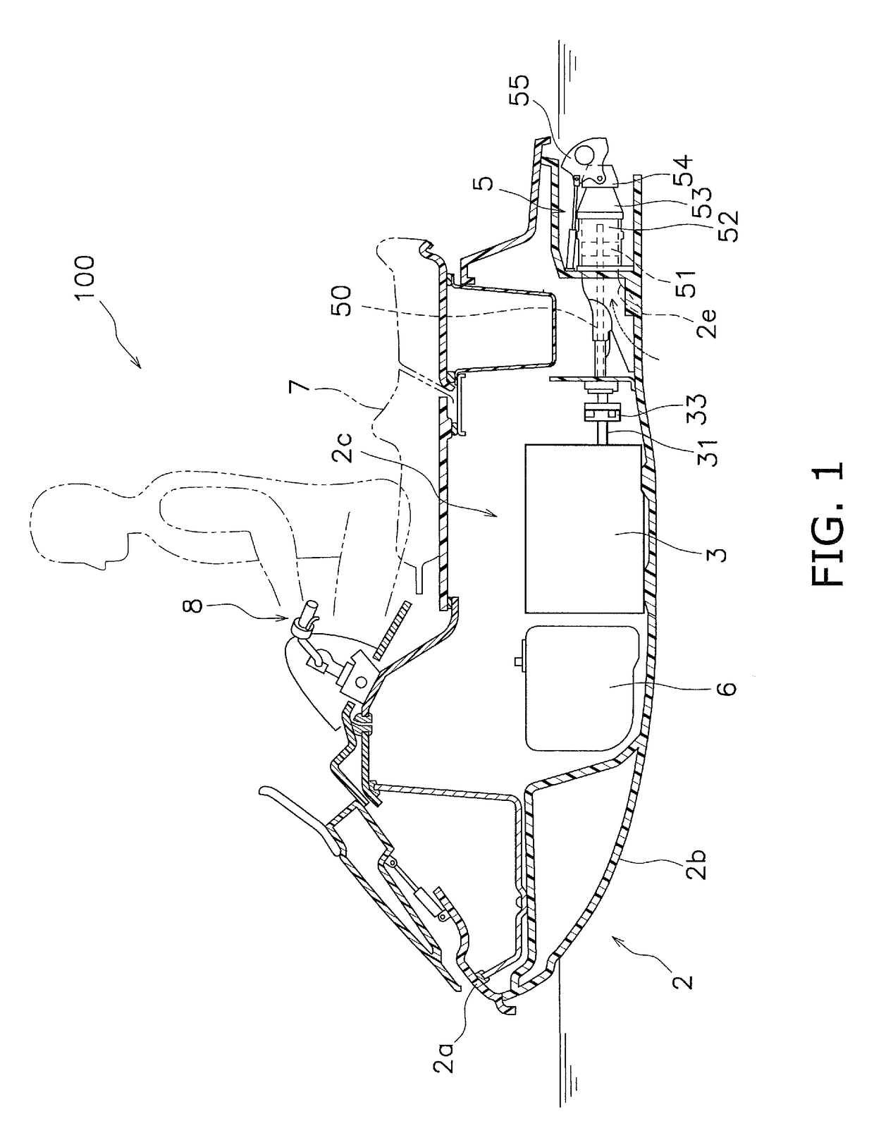
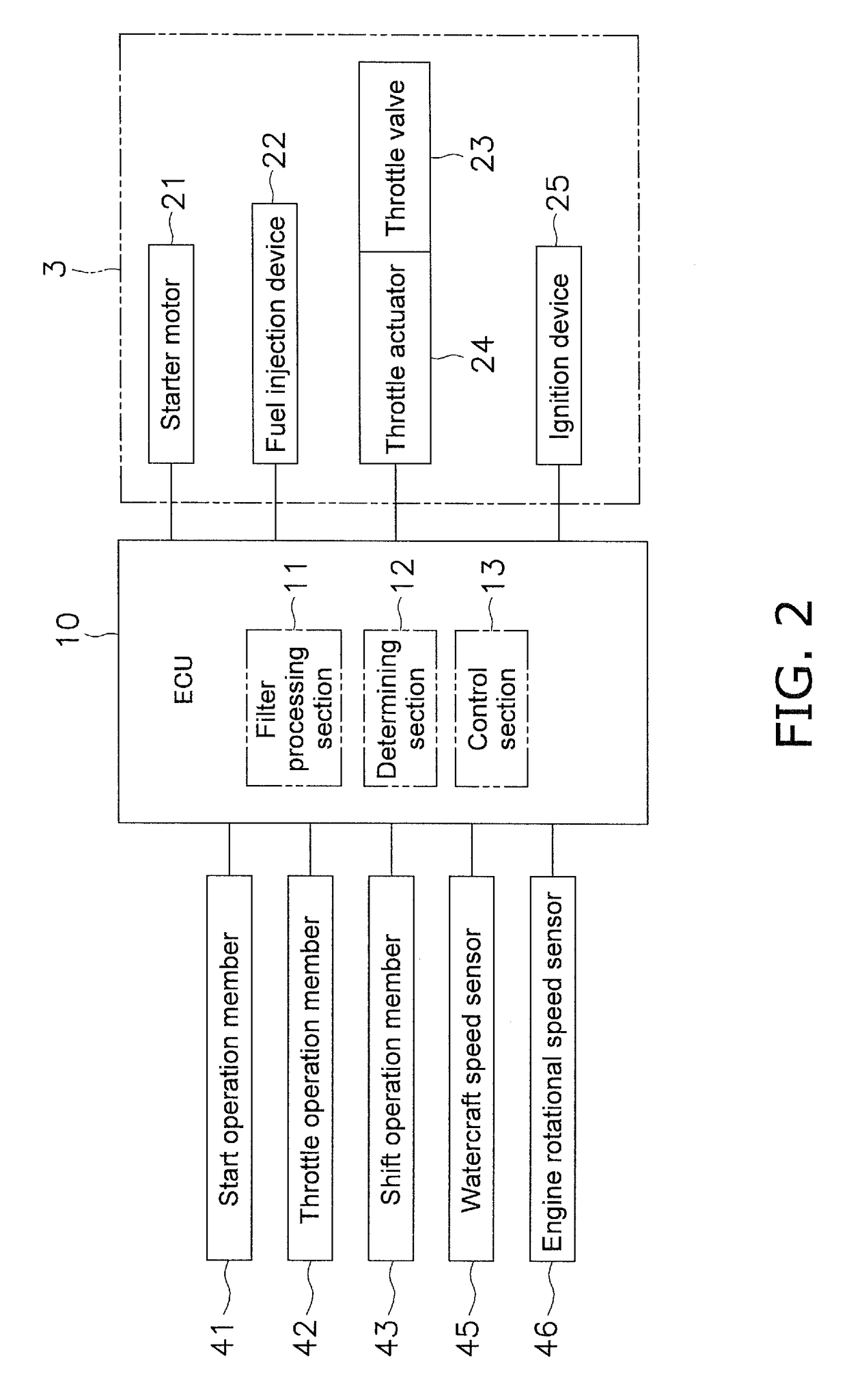
[0017]A watercraft according to preferred embodiments of the present invention will now be explained with reference to the drawings. FIG. 1 is a sectional view schematically showing constituent features of a watercraft 100 according to a preferred embodiment of the present invention. FIG. 2 is a block diagram showing a control system of the watercraft 100. The watercraft 100 is preferably a so-called personal watercraft (PWC), for example. As shown in FIG. 1, the watercraft 100 includes a hull body 2, an engine 3, and a propulsion device 5. The hull body 2 includes a deck 2a and a hull 2b. An engine room 2c is provided inside the hull body 2. The engine 3 and a fuel tank 6 are housed inside the engine room 2c. A seat 7 is attached to the deck 2a. The seat 7 is arranged above the engine 3. A steering handle 8 arranged to steer the hull body 2 is arranged in front of the seat 7.

[0018]The engine 3 is preferably, for example, an inline, four-cylinder, four-stroke engine. The engine 3 in...


PUM


Abstract

In a watercraft, an engine rotational speed sensor detects a rotational speed of an engine. A determining section determines if a prescribed execution condition indicating that a hull body is moving is satisfied. A filter processing section applies a filter process to the engine rotational speed detected by the engine speed sensor to acquire a filtered engine rotational speed. A control section executes a maximum speed limiting control to limit a maximum speed of the watercraft when the prescribed execution condition is satisfied and the filtered engine rotational speed is larger than a prescribed rotational speed threshold value.

Description

BACKGROUND OF THE INVENTION[0001]1. Field of the Invention[0002]The present invention relates to a watercraft.[0003]2. Description of the Related Art[0004]Regarding watercrafts, there is a maximum speed limiting control that limits a maximum speed of the watercraft. For example, the watercraft disclosed in U.S. Pat. No. 7,315,779 includes an ECU and a watercraft speed sensor that detects a watercraft speed. The watercraft speed sensor detects an engine rotational speed. If the watercraft speed sensor detects that the watercraft speed is larger than a prescribed maximum watercraft speed, then the ECU controls a throttle valve actuator such that an opening degree of a throttle valve is decreased. In this way, the maximum speed is limited.[0005]When a maximum speed limiting control is executed based on a detection value obtained with a watercraft speed sensor as explained above, the maximum speed limiting control is affected by the precision of the watercraft speed sensor. For example,...

Claims


Application Information

Patent Timeline
Patent Type & Authority Patents(United States)
IPC IPC(8): G06F19/00B63H21/00B63H11/00B63H21/21
CPCB63H21/24B63H11/00B63H2021/216
Inventor KINOSHITA, YOSHIMASA
Owner YAMAHA MOTOR CO LTD
Learn More