
Puller type card socket

a card socket and puller-type technology, applied in the field of puller-type card sockets, can solve the problems of impaired reliability of card insertion and contact with the contact terminal, complex and expensive fabrication, etc., and achieve the effect of simple structure, convenient withdrawal and simple structur

Inactive Publication Date: 2017-03-07
MOLEX INC
View PDF13 Cites 3 Cited by
  • Summary
  • Abstract
  • Description
  • Claims
  • Application Information

AI Technical Summary

Benefits of technology

[0006]The Present Disclosure has been devised in order to resolve the aforementioned disadvantages, and has, as an objective, providing a puller-type card socket that is configured to enable withdrawal of the card by a push-pull mechanism and straightforward withdrawal of the card from the front due to its structural simplicity, and that enables increased reliability of card insertion and reliability of contact with the contact terminals.
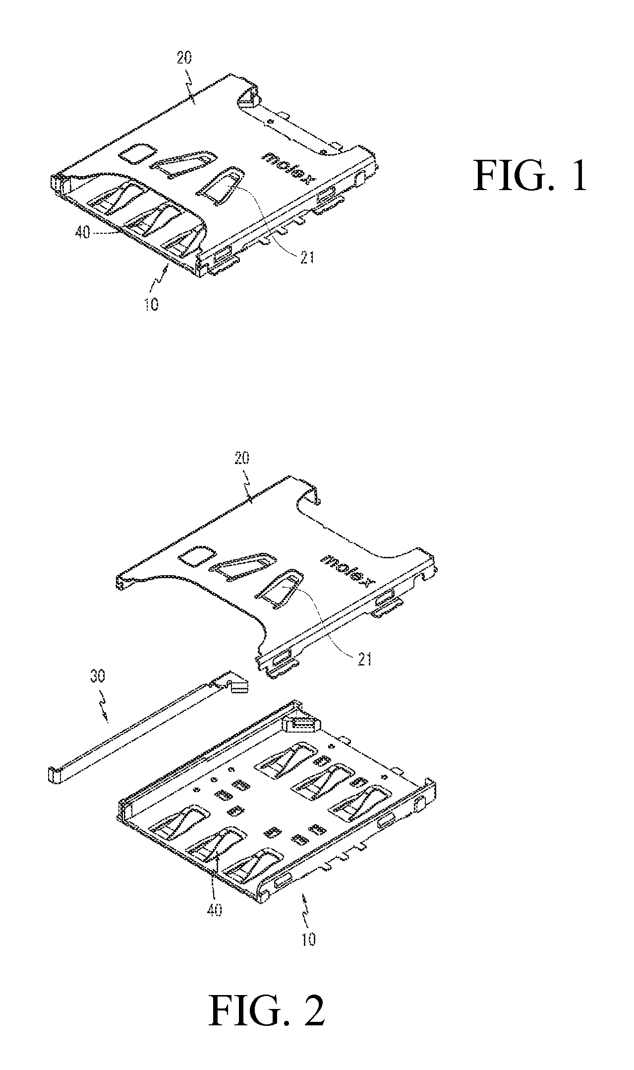
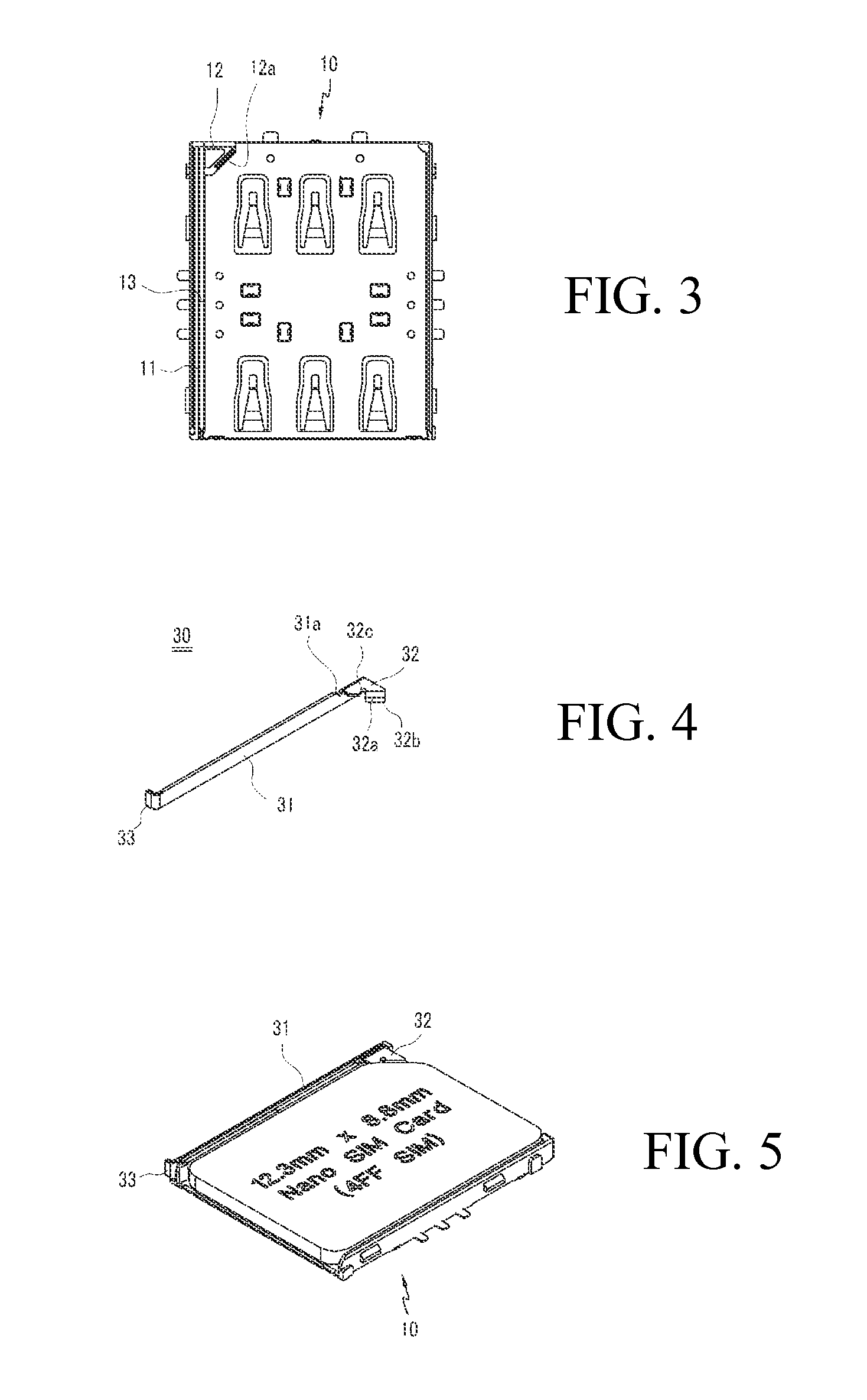
[0011]Thus, the puller-type card socket of the Present Disclosure has, inter alia, the following effects. First, it is configured to enable the card to be forcibly removed using a puller having a simple structure in a card socket with a push-pull mechanism. As a result, because it has a simpler structure than the card sockets with conventional push-pull mechanisms, the card can readily be withdrawn from the front of the housing, and the costs of fabrication are lower. As the unit cost of fabrication of the card socket is reduced, the unit cost of the mobile communication terminals using the socket is also reduced. Second, because it is configured so that the card contact part of the puller will overlap with the reverse mounting prevention part of the housing when the card has been fully inserted, the overall volume of the card socket can be greatly reduced, and the space into which the card is inserted can also be greatly reduced. Third, because a stopper is formed in the housing to restrict the forward sliding of the puller, the sliding range of the puller can be restricted so that the puller does not become completely separated from the card socket. Fourth, because a card pushing part is furnished on the cover by which the card is pushed, the insertion status of the card and the contact with the contact terminal can be kept stable. Fifth, because a card contact part, and a contact area expansion part formed on the card contact part, are formed as a single unit by bending from the sliding part and card contact part respectively, the fabrication of the puller can be facilitated.

Problems solved by technology

Push-push types, such as that disclosed in the '836 Patent, have the advantage that the card can be withdrawn more easily than in the push-pull type, but are problematic in that they are complex and expensive to fabricate.
In addition, because no separate configuration is disclosed for preventing the inserted card from slipping out, the reliability of card insertion and the reliability of contact with the contact terminals are impaired.

Method used


Image

  • Puller type card socket
  • Puller type card socket
  • Puller type card socket

Examples


Embodiment Construction

[0023]While the Present Disclosure may be susceptible to embodiment in different forms, there is shown in the Figures, and will be described herein in detail, specific embodiments, with the understanding that the Present Disclosure is to be considered an exemplification of the principles of the Present Disclosure, and is not intended to limit the Present Disclosure to that as illustrated.

[0024]As such, references to a feature or aspect are intended to describe a feature or aspect of an example of the Present Disclosure, not to imply that every embodiment thereof must have the described feature or aspect. Furthermore, it should be noted that the description illustrates a number of features. While certain features have been combined together to illustrate potential system designs, those features may also be used in other combinations not expressly disclosed. Thus, the depicted combinations are not intended to be limiting, unless otherwise noted.

[0025]In the embodiments illustrated in ...


PUM


Abstract

The puller type card socket of the Present Disclosure relates to a card socket furnished with a housing and a cover that covers the housing, configured so that a card can be inserted and withdrawn between the housing and the cover. A sliding part is mounted in a sliding groove formed on one side of the interior of the housing to enable sliding along the cover's insertion and withdrawal directions, and a card contact part is formed on the rear end of the sliding part so as to contact with and be pushed by the sloped front end of the card during insertion, and to push the card forward when the card is withdrawn A puller, wherein a pulling part is formed on the front part, is located at the front of the housing to be pulled on when withdrawing the card The card contact part is configured to overlap with the reverse mounting prevention part that prevents reverse mounting of the card when the card has been fully inserted, while on the top of one side wall of the sliding groove, a stopper part is formed that restricts the forward movement of the puller by catching on the card contact part of the puller when the card is withdrawn.

Description

REFERENCE TO RELATED APPLICATIONS[0001]The Present Disclosure claims priority to prior-filed Korean Patent Application No. 10-2014-0031136, entitled “Puller Type Card Socket,” filed on 17 Mar. 2014 with the Korean Patent Office. The content of the aforementioned Patent Application is incorporated in its entirety herein.BACKGROUND OF THE PRESENT DISCLOSURE[0002]The Present Disclosure relates, generally, to a card socket used in mobile communication terminals, in which cards are inserted and removed by a push-pull mechanism, and, more specifically, to a puller-type card socket wherein the card can readily be withdrawn from the front of the housing.[0003]On mobile communication terminals, authentication cards that enable authentication with respect to personal information and credit transactions, and memory cards for storing data when using diverse kinds of content, are respectively furnished. In the main body of the mobile communication terminal, a card socket for inserting a card is ...

Claims


Application Information

Patent Timeline
Patent Type & Authority Patents(United States)
IPC IPC(8): G06K13/08G06K7/00H01R13/633
CPCH01R13/6335G06K7/0069G06K13/08
Inventor JOO, SUNG-HYUK
Owner MOLEX INC
Learn More