
Sensor, measuring device, and measuring method

a technology of measuring device and measuring field, which is applied in the direction of instruments, dielectric property measurements, liquid/fluent solid measurements, etc., can solve the problems of reducing the quality of measuring field and degrading the measurement, and achieve the effect of low measuring frequency

Active Publication Date: 2017-03-07
SENFIT
View PDF14 Cites 3 Cited by
  • Summary
  • Abstract
  • Description
  • Claims
  • Application Information

AI Technical Summary

Benefits of technology

This approach reduces stray fields, enhances measuring accuracy, and allows for effective low-frequency measurements, improving the quality of the measuring field and reducing interference, thereby providing more reliable results in applications such as biomaterial hygrometry and dry content measurement.

Problems solved by technology

However, in the chambers of measuring devices utilizing helix resonance, there are strong stray fields, which reduces the quality of the measuring field and degrades the measuring result.

Method used


Image

  • Sensor, measuring device, and measuring method
  • Sensor, measuring device, and measuring method
  • Sensor, measuring device, and measuring method

Examples


Embodiment Construction

[0023]The following embodiments are presented by way of example. Even though the description may refer to “an” embodiment at different points, this does not necessarily mean that each such reference is to the same embodiment or that a feature only applies to one embodiment, but instead individual features of different embodiments may also be combined to produce other embodiments.

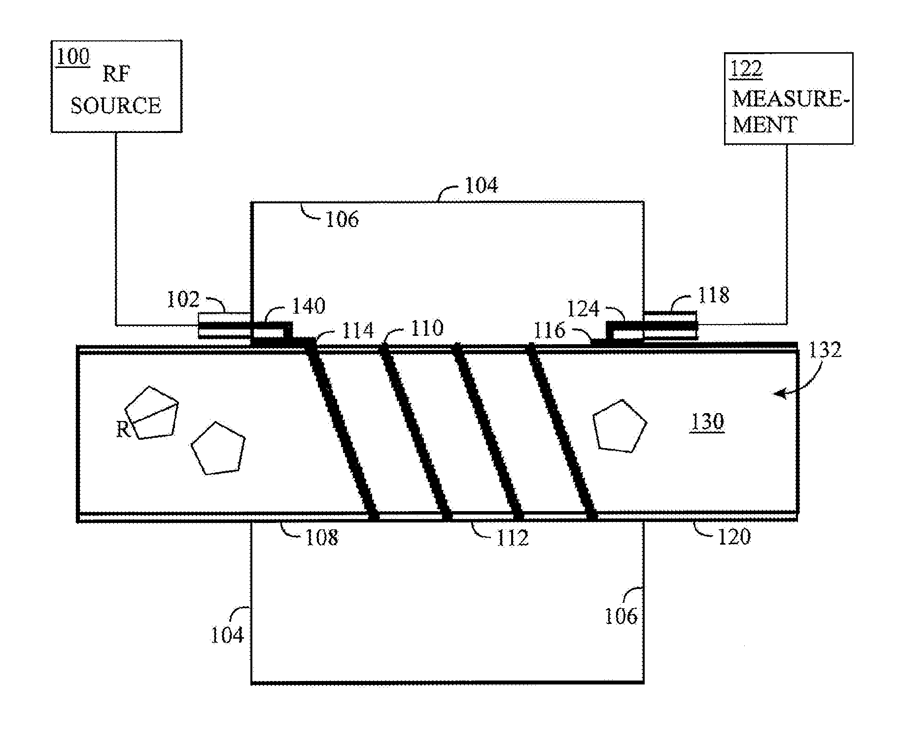
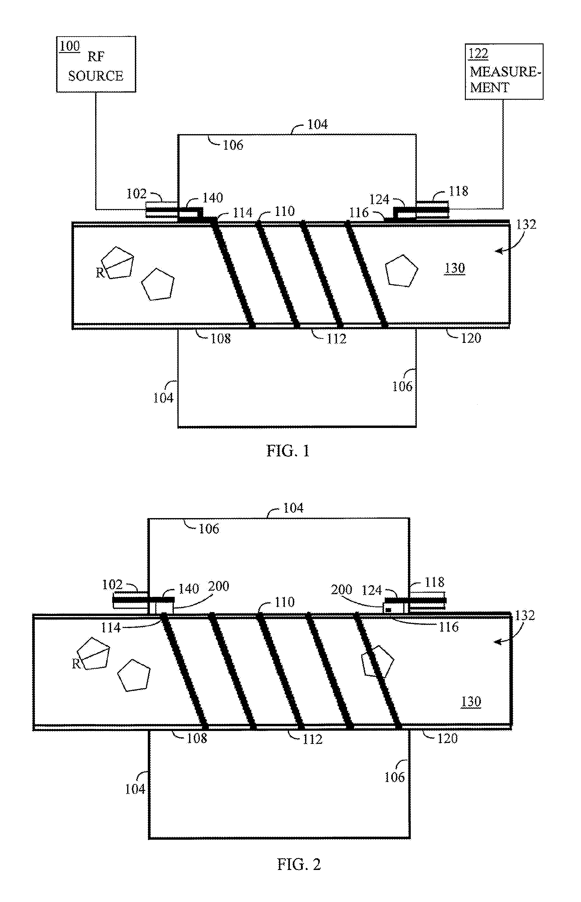
[0024]Let us first examine an example of a measuring sensor and device by means of FIG. 1. A radio-frequency signal source 100 supplies a radio-frequency signal to an input element 102 that comprises a coaxial connector or microstrip structure or some other transmission conductor structure. In an embodiment, the radio-frequency source 100 may sweep over the frequency range being measured. In an embodiment, the measuring is based on self-oscillation, in which a radio-frequency signal entering and exiting the sensor is coupled to an amplifying element in such a manner that an oscillation circuit is created to ...


PUM

PropertyMeasurementUnit
widthaaaaaaaaaa
lengthaaaaaaaaaa
lengthaaaaaaaaaa

Abstract

A sensor measures a sample in a measuring cell including a helix conductor. The shell structure of the measuring cell is made of an electrically non-conductive material. The measuring cell and at least part of the helix conductor are placeable inside a chamber. A radio-frequency signal input element couples a radio-frequency signal to the chamber to form a helix resonance. A radio-frequency signal output element is responsive to a helix resonance of the helix conductor and transmits a radio-frequency signal for measurement. A device for measuring a sample in a measuring cell includes the sensor, a radio-frequency signal source, and a measuring and control part. The radio-frequency signal source produces a radio-frequency signal to the input element. The measuring and control part measures a property of a sample on the basis of a resonance frequency.

Description

CROSS-REFERENCE TO RELATED APPLICATION[0001]This application claims benefit to Finnish Application No. FI 20145503, filed Jun. 2, 2014, which is incorporated by reference herein in its entirety.BACKGROUND[0002]Field[0003]The invention relates to a sensor, measuring device, and measuring method.[0004]Description of the Related Art[0005]A helix resonator has a helical conductor (helix) in an electrically conductive chamber. The radio-frequency resonance of the helix resonator depends, among other things, on the permittivity of the material inside the helical conductor. In the prior art, helix resonance has been used in hygrometry, for example.[0006]However, in the chambers of measuring devices utilizing helix resonance, there are strong stray fields, which reduces the quality of the measuring field and degrades the measuring result. In other respects, too, there is a need to further develop resonance measurement utilizing a helical conductor.SUMMARY[0007]The object of the invention is...

Claims


Application Information

Patent Timeline
Patent Type & Authority Patents(United States)
IPC IPC(8): G01R27/04G01N27/22G01R27/28G01R27/06G01N22/04G01R27/32G01R31/11G01F1/66
CPCG01N22/04G01N27/221G01R27/06G01R27/28G01N27/223G01R31/11G01F1/58H01P7/005G01F1/662G01R27/2658G01R27/267
Inventor JAKKULA, PEKKAVUOLTEENAHO, MIKKOKORHONEN, MARKKUFISK, VESA
Owner SENFIT
Learn More