
Spatial audio rendering and encoding

a technology of spatial audio and encoding, applied in the field of spatial audio rendering and/or encoding, can solve the problems of inability to faithfully render diffuse signal components, inability of channel based audio coding systems to cope with a different number of speakers, and inability to provide normative means to transmit audio scenes, etc., to achieve advantageous diffuse sound rendering, improve user experience, and improve the effect of diffuse sound

Inactive Publication Date: 2017-02-28
KONINK PHILIPS ELECTRONICS NV
View PDF19 Cites 9 Cited by
  • Summary
  • Abstract
  • Description
  • Claims
  • Application Information

AI Technical Summary

Benefits of technology

[0024]The invention may provide improved audio rendering. In particular, it may in many embodiments and for many different audio scenes and rendering setups provide an improved audio quality and user experience. In many scenarios the approach may in particular provide an improved rendering of residual downmixes with improved consideration of spatial characteristics of different audio components of the residual downmix.
[0063]The invention may be particularly suitable for adapting a specific (residual) downmix to a different speaker configuration. The approach may provide for a system which allows improved and flexible adaptation to different speaker setups.

Problems solved by technology

Also, these channel based audio coding systems are typically not able to cope with a different number of speakers.
However the provided methods rely on either fixed reproduction setups or on unspecified syntax.
Thus SAOC does not provide normative means to transmit an audio scene independently of the speaker setup.
More importantly, SAOC is not well equipped to the faithful rendering of diffuse signal components.
A critical problem is how to handle such different audio types and in particular how to handle such different types of audio in different speaker configurations.
However, although such approaches may be advantageous over channel based approaches, the rendering of diffuse sound sources at different speaker configurations is suboptimal.
However, although DirAC provides an approach that may improve audio quality over some systems that do not consider separate processing of spatially defined sound sources and diffuse sounds, it tends to provide suboptimal sound quality.
In particular, when adapting the system to different speaker configurations, the specific rendering of diffuse sounds based only on a relatively simple division of downmix signals into diffuse / non-diffuse components tend to result in a less than ideal rendering of the diffuse sound.
Therefore, it is not possible to e.g. generate a truly diffuse signal in the presence of point sources.

Method used


Image

  • Spatial audio rendering and encoding
  • Spatial audio rendering and encoding
  • Spatial audio rendering and encoding

Examples


Embodiment Construction

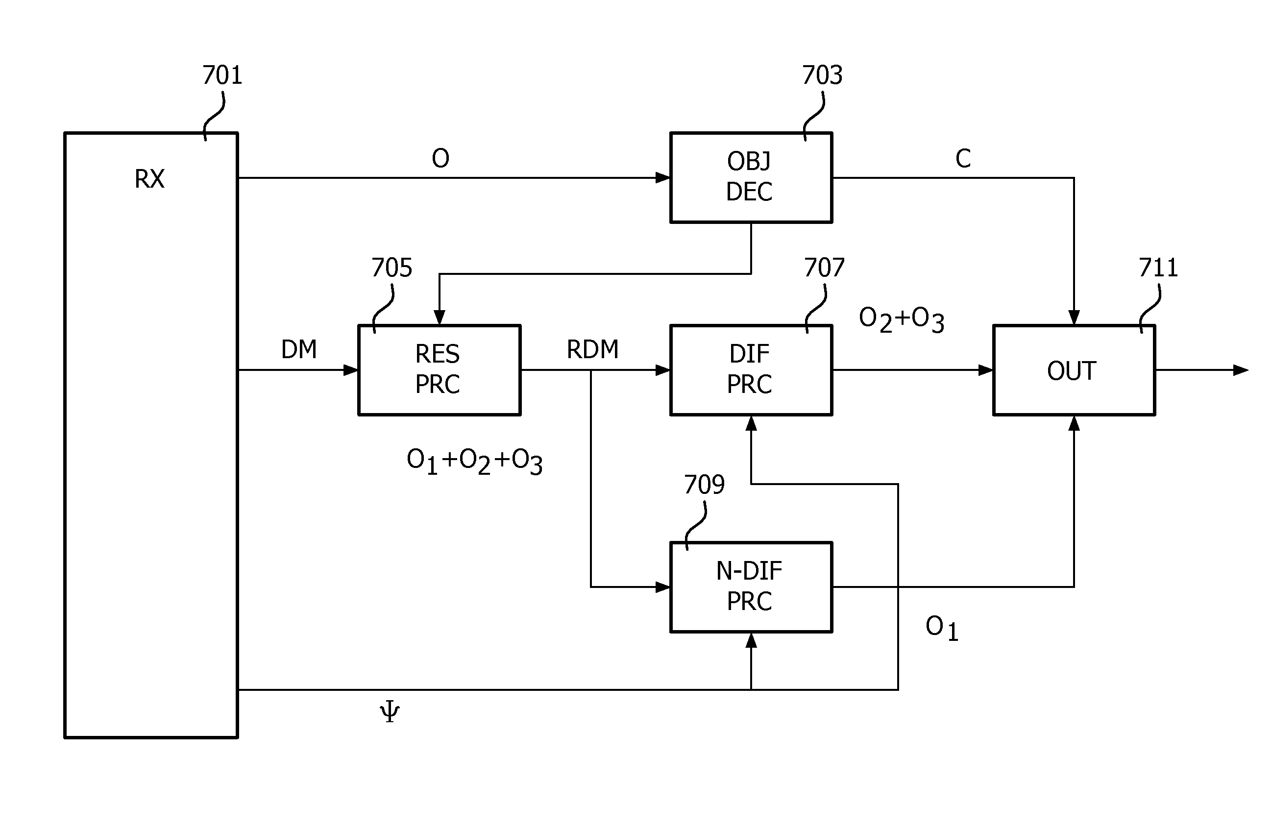
[0078]FIG. 5 illustrates an example of an audio rendering system in accordance with some embodiments of the invention. The system comprises a spatial audio encoding device 501 which receives audio information to be encoded. The encoded audio data is transmitted to a spatial audio rendering device 503 via a suitable communication medium 505. The spatial audio rendering device 503 is furthermore coupled to a set of speakers associated with a given spatial speaker configuration.

[0079]The audio data provided to the spatial audio encoding device 501 may be provided in different forms and generated in different ways. For example, the audio data may be audio captured from microphones and / or may be synthetically generated audio such as for example for computer games applications. The audio data may include a number of components that may be encoded as individual audio objects, such as e.g. specific synthetically generated audio objects or microphones arranged to capture a specific audio sou...


PUM

PropertyMeasurementUnit
angleaaaaaaaaaa
energyaaaaaaaaaa
distanceaaaaaaaaaa

Abstract

An encoder (501) generates data representing an audio scene by a first downmix and data characterizing audio objects. In addition, a direction dependent diffuseness parameter indicative of a degree of diffuseness of a residual downmix is provided where the residual downmix corresponds to a downmix of audio components of the audio scene with the audio objects being extracted. A rendering apparatus (503) comprises a receiver (701) receiving the data from the encoder (501). A circuit (703) generates signals for a spatial speaker configuration from the audio objects. A transformer (709) generates non-diffuse sound signals for the spatial speaker configuration by applying a first transformation to the residual downmix and another transformer (707) generates signals for the spatial speaker configuration by applying a second transformation to the residual downmix by applying a decorrelation to the residual downmix. The transformations are dependent on the direction dependent diffuseness parameter. The signals are combined to generate an output signal.

Description

FIELD OF THE INVENTION[0001]The invention relates to spatial audio rendering and / or encoding, and in particular, but not exclusively, to spatial audio rendering systems with different spatial speaker configurations.BACKGROUND OF THE INVENTION[0002]Digital encoding of various source signals has become increasingly important over the last decades as digital signal representation and communication increasingly has replaced analogue representation and communication. For example, audio content, such as speech and music, is increasingly based on digital content encoding.[0003]Audio encoding formats have been developed to provide increasingly capable, varied and flexible audio services and in particular audio encoding formats supporting spatial audio services have been developed.[0004]Well known audio coding technologies like DTS and Dolby Digital produce a coded multi-channel audio signal that represents the spatial image as a number of channels that are placed around the listener at fixe...

Claims


Application Information

Patent Timeline
Patent Type & Authority Patents(United States)
IPC IPC(8): G01L19/00G10L19/008H04R3/12G10L19/20G10L19/00H04S3/00
CPCH04R3/12G10L19/00G10L19/008G10L19/20H04S3/002H04R2430/00H04S3/004H04S3/008H04S2400/11H04S2420/01H04S7/308H04S2400/03
Inventor KOPPENS, JEROEN GERARDUS HENRICUSSCHUIJERS, ERIK GOSUINUS PETRUSOOMEN, ARNOLDUS WERNER JOHANNESVAN DE KERKHOF, LEON MARIA
Owner KONINK PHILIPS ELECTRONICS NV
Learn More