
Pneumatic driven two-axis motion platform

a two-axis, motion platform technology, applied in the direction of amusements, instruments, auditorium chairs, etc., can solve the problems of large volume, large number of parts, and two-axis dynamic simulation devices using hydraulic technology, and achieve simple assembly and maintenance, the effect of reducing manufacturing costs

Inactive Publication Date: 2017-02-28
INJOY MOTION
View PDF5 Cites 0 Cited by
  • Summary
  • Abstract
  • Description
  • Claims
  • Application Information

AI Technical Summary

Benefits of technology

The present invention provides a pneumatic driven two-axis motion platform that has a simpler structure and fewer components, making it easier to assemble and maintain. It uses bag-shaped telescopic modules instead of four sets used in previous devices, reducing manufacturing costs. The platform is particularly useful for light-duty applications.

Problems solved by technology

However, the two-axis dynamic simulation devices using hydraulic technology have disadvantages regarding bulky volume, numerous parts required, difficult for assembling works, and inconvenient for frequent maintenance.
On the other hand, the two-axis dynamic simulation devices using one or more driving motors are difficult for assembling works due to too many components.
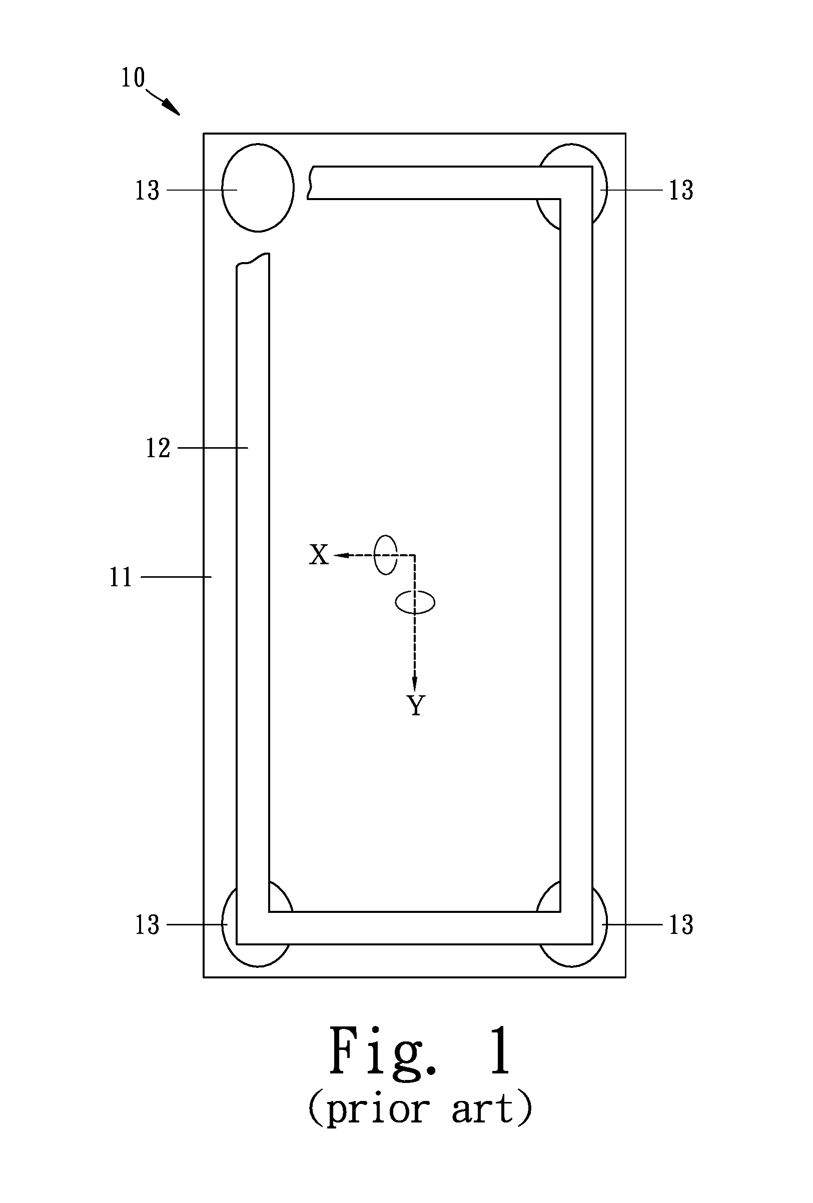
Such an arrangement, however, may cause a hindrance or obstruction in doing two-axis dynamic motion among the four bag-shaped telescopic modules 13.
Nevertheless, the pneumatic driven gasbag-type motion platform 10 is impossible to generate a two-axis rotation that has two dimensions of freedom about X-axis or / and Y-axis directions, thus inevitably to cause the application scope of the pneumatic driven gasbag-type motion platform 10 being limited.
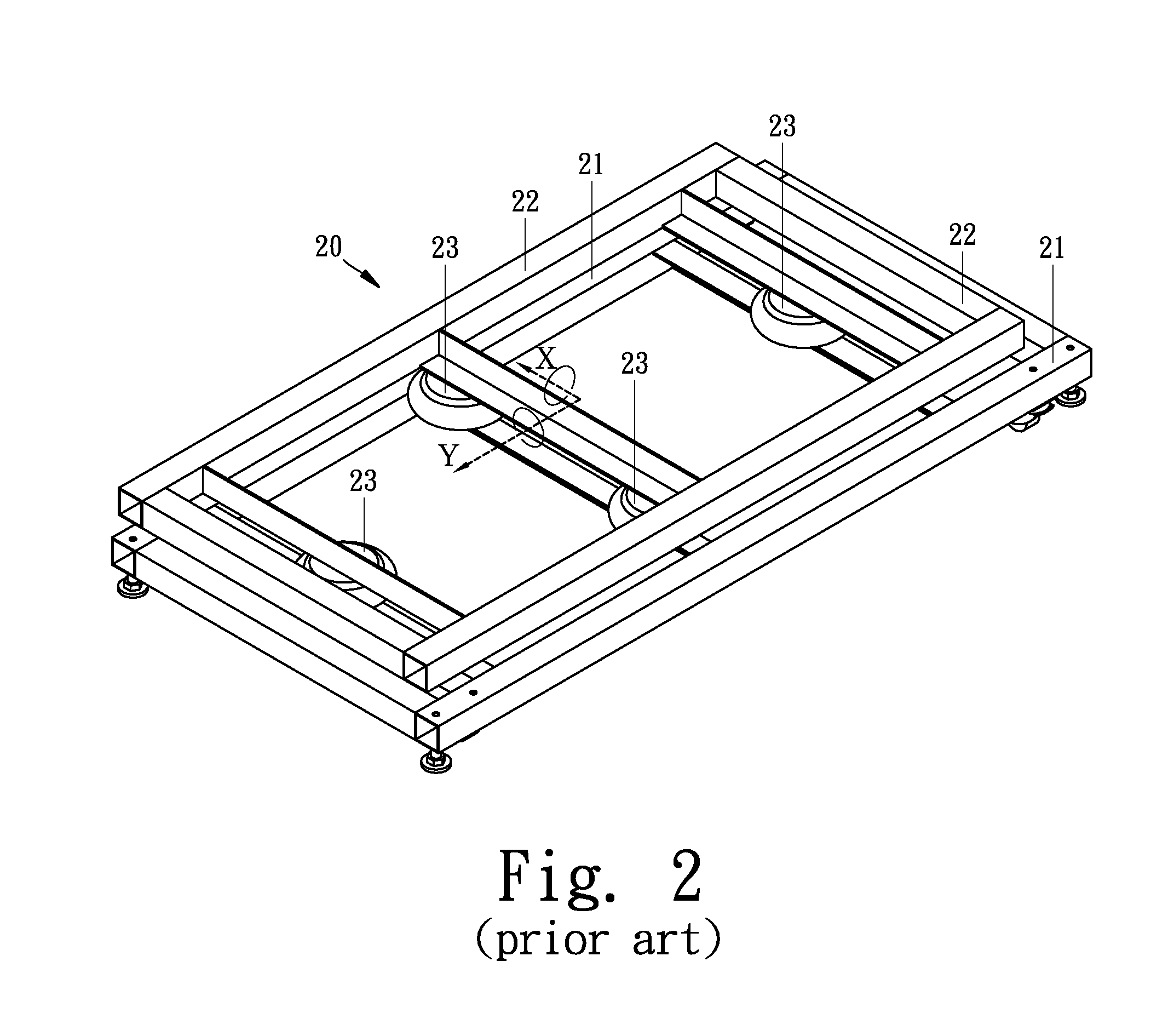
However, in consideration of both cost-benefit and maintenance-benefit, the pneumatic driven gasbag-type motion platform 20 of FIG. 2 due to indispensably using four sets of bag-shaped telescopic modules 23 has unavoidable defects in high manufacturing cost and high maintenance fee.

Method used


Image

  • Pneumatic driven two-axis motion platform
  • Pneumatic driven two-axis motion platform
  • Pneumatic driven two-axis motion platform

Examples


Embodiment Construction

[0032]Now, preferred embodiments of the present invention will be described in detail with reference to the annexed drawings.

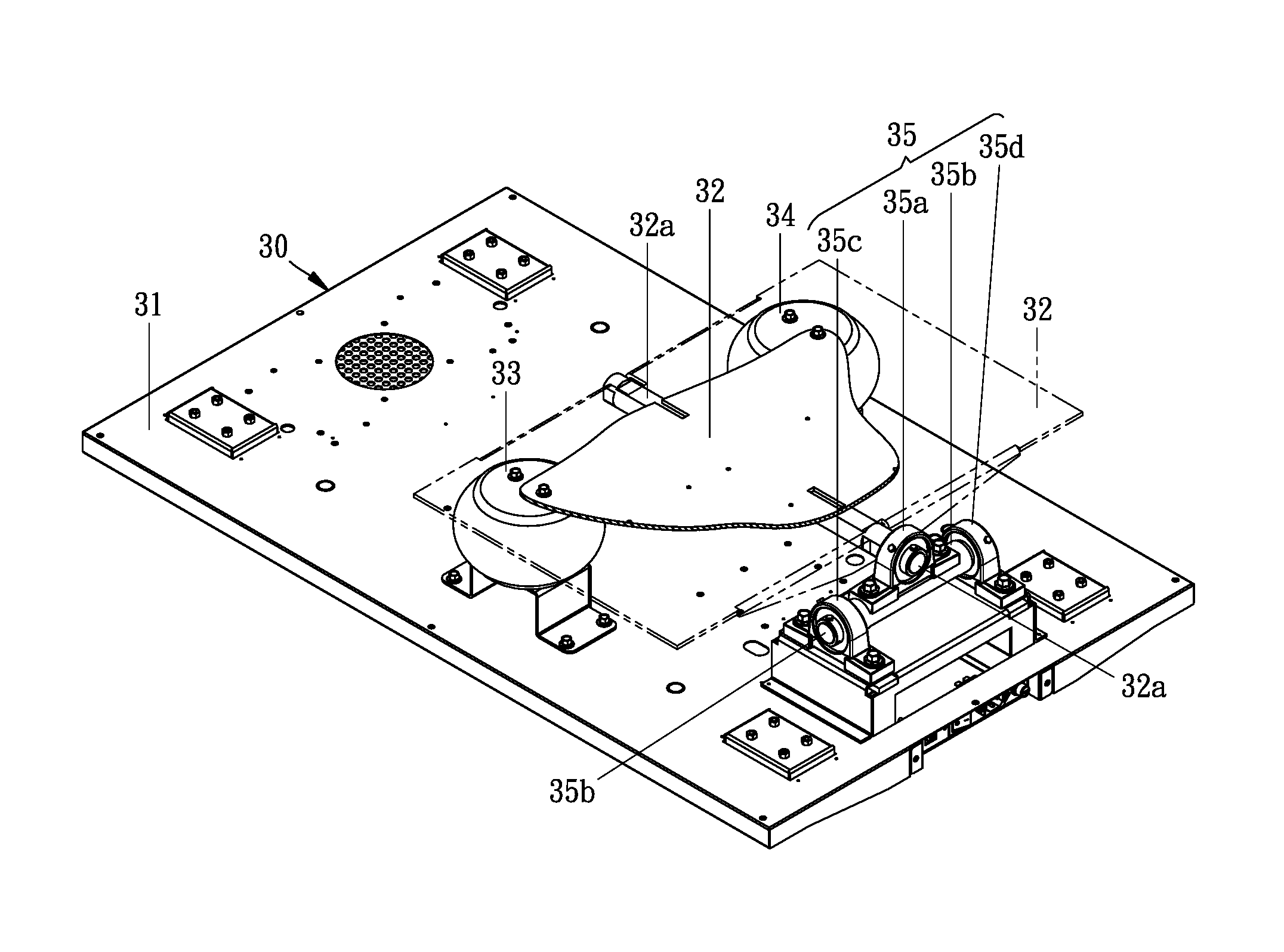
[0033]As shown in from FIG. 3 to FIG. 5, a first embodiment of a pneumatic driven two-axis motion platform (hereinafter abbreviated as two-axis motion platform) 30 of the present invention is disclosed to use two sets of bag-shaped telescopic modules 33 and 34, compared with the prior known pneumatic driven gasbag-type motion platform 10 (or 20) of FIG. 1 (or FIG. 2) which is taught to use four sets of bag-shaped telescopic modules 13 (or 23).

[0034]As shown in FIG. 3 and FIG. 4, the two-axis motion platform 30 of the present invention comprises a foundation base 31, a movable table 32, two sets of bag-shaped telescopic modules 33 and 34, and a two-way orthogonal rotator 35, wherein the movable table 32 as shown in FIG. 5 through FIG. 7 has two dimensions of rotational freedom about X-axis or / and Y-axis (hereinafter referred to as two-axis rotation).

[0035]As sh...


PUM


Abstract

A pneumatic driven two-axis motion platform is structurally simple for using two bag-shaped telescopic modules spaced apart and fixed to a foundation base being laid on the ground, and a movable table having a pivotal shaft used for making a pivotal connection with a two-way orthogonal rotator, after completely assembled, the movable table is mounted on the two bag-shaped telescopic modules by such arrangement that the two bag-shaped telescopic modules are symmetrical against the pivotal shaft of the movable table, and the two-way orthogonal rotator is arranged together with the two bag-shaped telescopic modules as an isosceles triangle arrangement; by such structural arrangement, said two-axis motion platform is endowed with two dimensions of rotational freedom when pneumatic inflating or deflating one or both of the two bag-shaped telescopic modules.

Description

BACKGROUND OF THE INVENTION[0001]1. Field of the Present Invention[0002]The present invention relates to a pneumatic motion platform, and more particularly to a pneumatic driven two-axis motion platform which uses as few as two sets of bag-shaped telescopic modules.[0003]2. Description of Related Art[0004]Traditional two-axis dynamic simulation devices, such as 3D dynamic simulation devices for use in simulation of aviation or car racing, usually either adopt hydraulic technology or use one or more driving motors to hydraulically or mechanically drive the two-axis dynamic simulation device to be moved in one-axis motion or in two-axis motion along two axes at the same time.[0005]However, the two-axis dynamic simulation devices using hydraulic technology have disadvantages regarding bulky volume, numerous parts required, difficult for assembling works, and inconvenient for frequent maintenance.[0006]On the other hand, the two-axis dynamic simulation devices using one or more driving ...

Claims


Application Information

Patent Timeline
Patent Type & Authority Patents(United States)
IPC IPC(8): A63G31/16A47C1/12
CPCA63G31/16A63J5/00A63G31/12G09B9/02
Inventor CHIANG, JOHNSONWU, PING-LINCHANG, SONG-KUEI
Owner INJOY MOTION
Learn More