Method for controlling a load-moving device and controller of a load-moving device

a technology of a load-moving device and a controller, which is applied in the direction of load-engaging elements, transportation and packaging, etc., can solve the problems of crane operators having to correctly interpret acoustic signals, the difficulty of locating bankers, so as to reduce the risk of accidents

Active Publication Date: 2017-02-14
LIEBHERR WERK NENZING
View PDF26 Cites 1 Cited by
  • Summary
  • Abstract
  • Description
  • Claims
  • Application Information

AI Technical Summary

Benefits of technology

[0043]The present invention thus provides two equivalent operating units, by means of which the load-moving device each can be controlled without a reduction in safety. Advantageously, the load-moving device also can be operated alone via the first operating unit or the mobile operating unit.
[0044]Advantageously, the mobile operating unit in the controller of the invention is a radio remote control. This provides a maximum of mobility for the machine operator operating the mobile operating unit, who can move around freely.

Problems solved by technology

In many cases, however, the banksman cannot be positioned such that he both has a good view of the load and yet is visible and recognizable for the crane operator.
In this connection it is disadvantageous that the crane operator must correctly interpret an acoustic message, which especially as regards the direction to be taken is much more difficult and error-prone than the known hand signals.
Known radio remote controls, e.g. for tower cranes, by means of which the machine operator himself instead of the banksmen can perform fine positioning of the load, are no remedy, since the operator then would no longer have the overview necessary for otherwise moving the load.
Since the person with the mobile operating unit usually is positioned close to the load and thus is particularly endangered, this ensures that this person cannot loose control over the load-moving device without action on his part.
On the other hand, switching on the mobile operating unit during operation of the load-moving device is impossible, which in turn increases safety.

Method used


Image

  • Method for controlling a load-moving device and controller of a load-moving device
  • Method for controlling a load-moving device and controller of a load-moving device
  • Method for controlling a load-moving device and controller of a load-moving device

Examples


Embodiment Construction

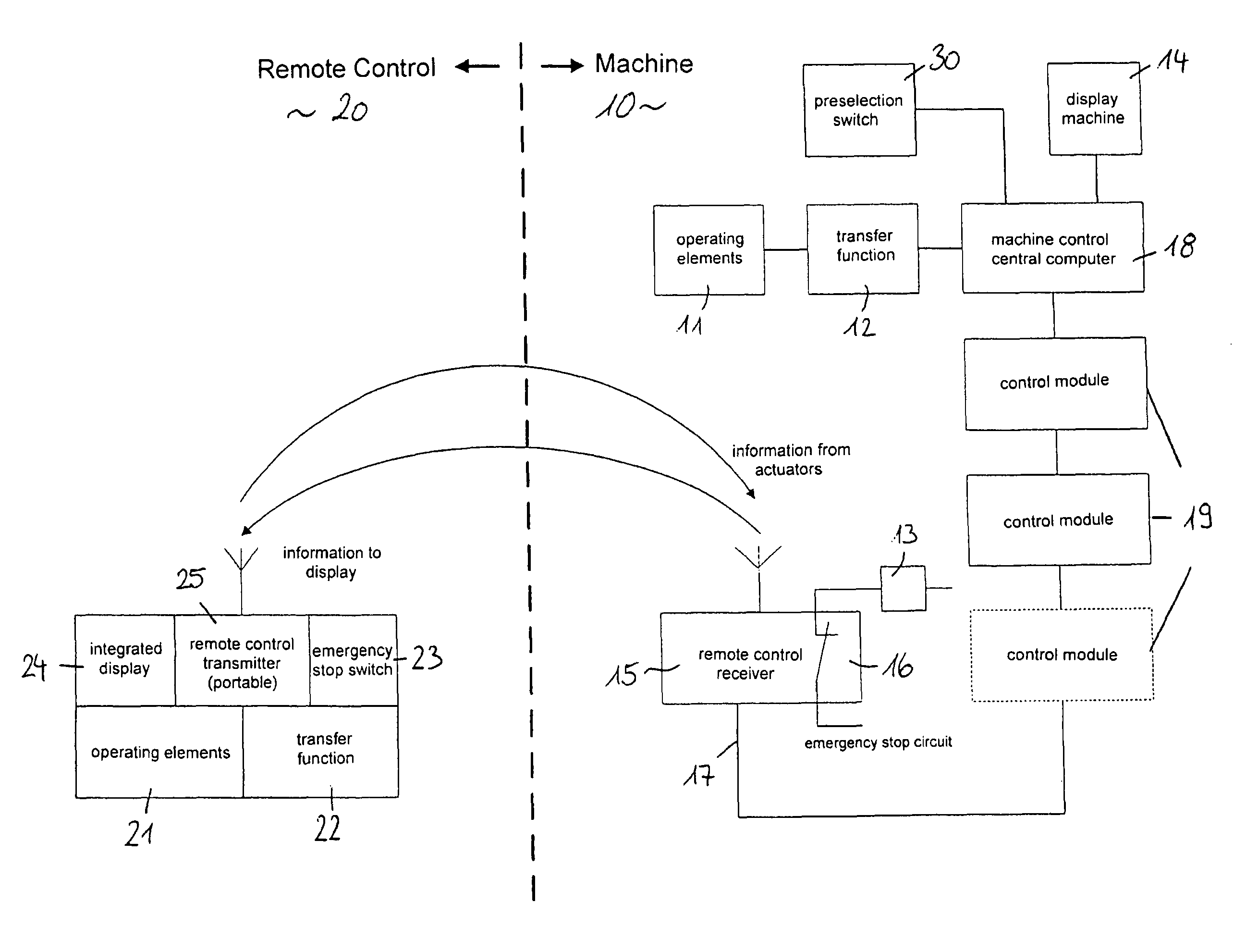
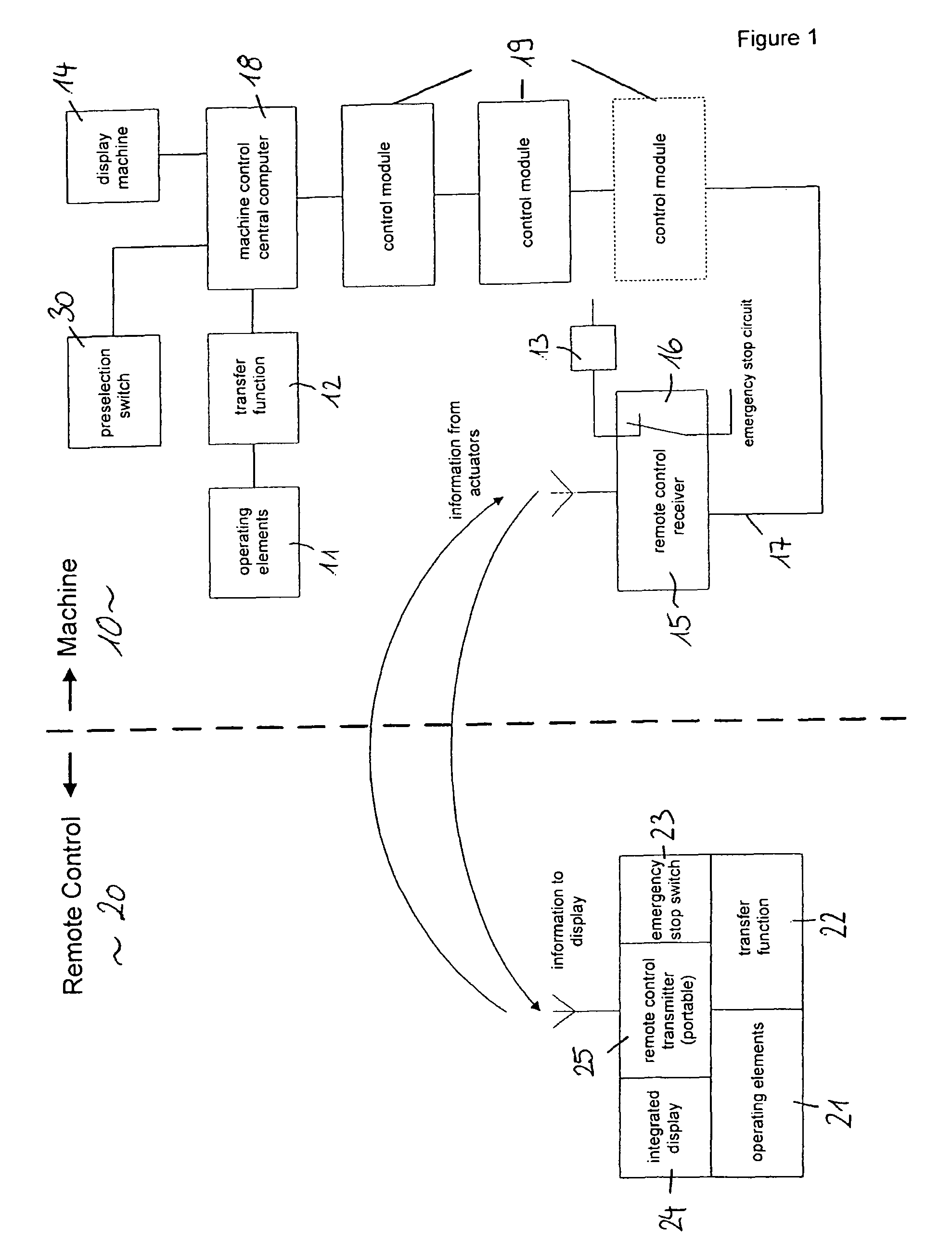
[0052]The controller of the present invention is used in a crawler crane, in which the control station arranged in the crane operator cabin, which represents the first operating unit, is very far away from the load to be positioned, so that for certain tasks actuation can be effected more favorably via the second, mobile operating unit.

[0053]FIG. 1 only shows one embodiment of the control of the invention with a first, permanently installed operating unit 10 and a second mobile operating unit 20. Both operating units include operating elements 11, 21 for actuating the movement of the load-moving device, which are configured as corresponding actuators for initiating machine movements. Both operating units likewise include a display 14, 24, on which all information necessary and prescribed for operating the load-moving device is represented. Furthermore, both operating units include an emergency stop switch 13, 23, by means of which an emergency stop of the load-moving device can be i...


PUM


Abstract

The present invention comprises a method for controlling a load-moving device by at least two persons, with the following steps: controlling the movement of the load-moving device by a first person; handing over control over the movement of the load-moving device to a second person; controlling the load-moving device by the second person. The present invention furthermore comprises a corresponding controller of a load-moving device with a first, in particular permanently installed operating unit and a mobile operating unit for controlling the movement of the load-moving device for the safe and efficient performance of the method.

Description

CROSS-REFERENCE TO RELATED APPLICATIONS[0001]This is the U.S. National Phase of International PCT Application Serial No. PCT / EP2008 / 003145, filed Apr. 18, 2008, which claims priority to German Patent Application No. 10 2007 018 646.2, filed on Apr. 19, 2007, both of which are hereby incorporated by reference in their entirety for all purposes.TECHNICAL FIELD[0002]The present invention relates to a method for controlling a load-moving device and a controller of a load-moving device. A load-moving device in the sense of the present invention is any kind of cargo handling or conveying device, in particular cranes and excavators. Particularly advantageously, the controller of the invention is used in crawler cranes, mobile cranes, cable excavators, harbor and ship cranes.BACKGROUND AND SUMMARY[0003]It is characteristic for great load-moving devices such as crawler cranes that the control station of the machine is very far away from the load to be positioned. Since in many cases the mach...

Claims


Application Information

Patent Timeline
Patent Type & Authority Patents(United States)
IPC IPC(8): B66C13/40
CPCB66C13/40
Inventor SCHMID, JOSEF KASPARSCHAPLER, MANFRED
Owner LIEBHERR WERK NENZING
Why Eureka
Try Eureka