Radar apparatus and method of measuring radar performance

a technology of radar apparatus and radar signal, which is applied in the field of radar apparatus, can solve the problems of slow transmission cycle of radar signal, deterioration of transmitters and receivers provided in radar apparatuses, and inability to update radar image while the performance of radar apparatus is measured

Active Publication Date: 2017-01-24
FURUNO ELECTRIC CO LTD
View PDF9 Cites 0 Cited by
  • Summary
  • Abstract
  • Description
  • Claims
  • Application Information

AI Technical Summary

Benefits of technology

[0010]The present invention is made in view of the above situations, and mainly aims to provide a radar apparatus, which measures performance of the radar apparatus while minimizing influence of the measurement on the radar image.
[0014]Thus, an operator can confirm the performance of, for example, the transmitter while suppressing the influence on the radar image.
[0017]The performance monitor may transmit a performance signal for measuring the performance of the receiver. The radar image generating module may compensate for the radar image that is not acquired while the performance signal is transmitted, with other radar image data.
[0022]Thus, the operator can instinctively grasp the time transition of the performance of, for example, the transmitter. Therefore, for example, it can easily be confirmed that it is required to replace a magnetron. Moreover, since the chart is displayed along with the radar image, the operator can confirm, for example, that it is required to replace the magnetron while confirming target(s) around the radar apparatus (i.e., without switching the display).
[0028]Thus, since importance of displaying an echo from a target located rearward of the movable body is low, the operator can confirm the performance of, for example, the transmitter while suppressing the influence on the radar image.
[0032]Thus, the performance of at least one of the transmitter and the receiver can be measured without stopping the update of the radar image. Moreover, by suspending the transmission of the radar signal, the performance signal can be transmitted at an arbitrary timing during the transception of the radar signal (e.g., a timing with less influence on the radar image).

Problems solved by technology

Transmitters (e.g., magnetrons) and receivers (e.g., electronic components of reception circuits) provided in radar apparatuses may deteriorate as being used, or be damaged by a strong signal received externally.
Here, in the case of measuring the performance of the radar apparatus by switching the mode as disclosed in JP2011-117808A, there is a disadvantage that the radar image cannot be updated while the performance of the radar apparatus is measured.
However, with the radar apparatus in JP2011-117809A, there has been a problem that a transmission cycle of the radar signal becomes slow.
Especially when a radar signal with a long pulse width is transmitted for long distance detection, since a detection range in an azimuth direction becomes wider, a problem arises that the echo cannot be detected in a large area.
Moreover, in the radar apparatus of JP2011-117809A, even if the transmission cycle of the radar signal is shortened by sacrificing the reflection echo of the radar signal from a long distance area, a problem arises that a target at a distant location from the radar apparatus cannot be displayed.

Method used


Image

  • Radar apparatus and method of measuring radar performance
  • Radar apparatus and method of measuring radar performance
  • Radar apparatus and method of measuring radar performance

Examples


Embodiment Construction

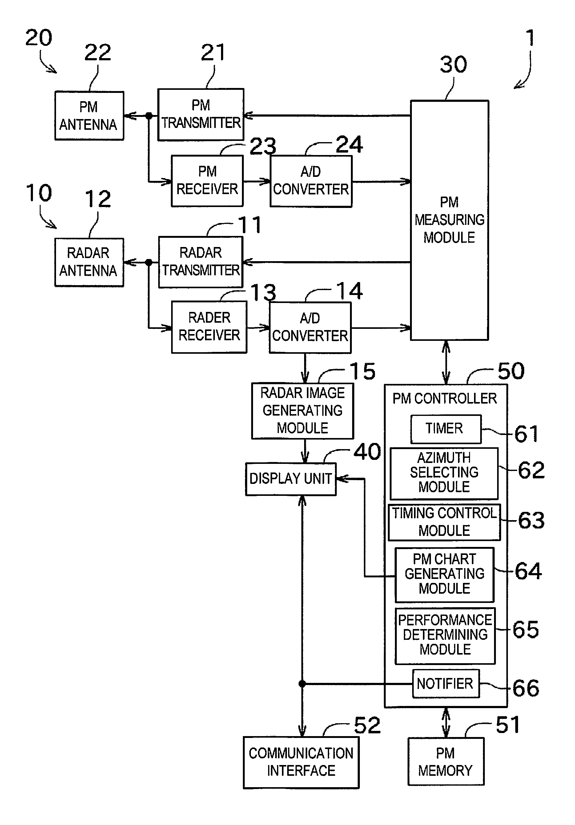
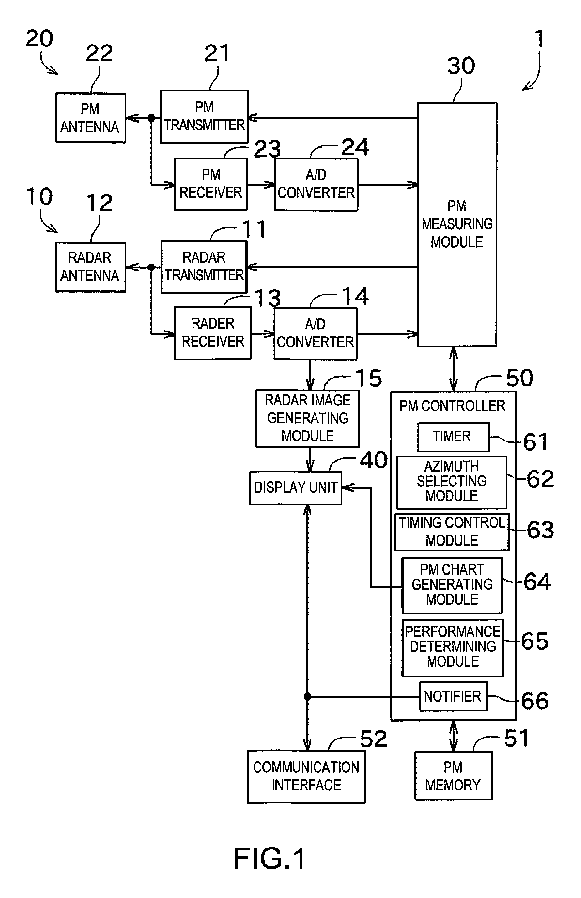
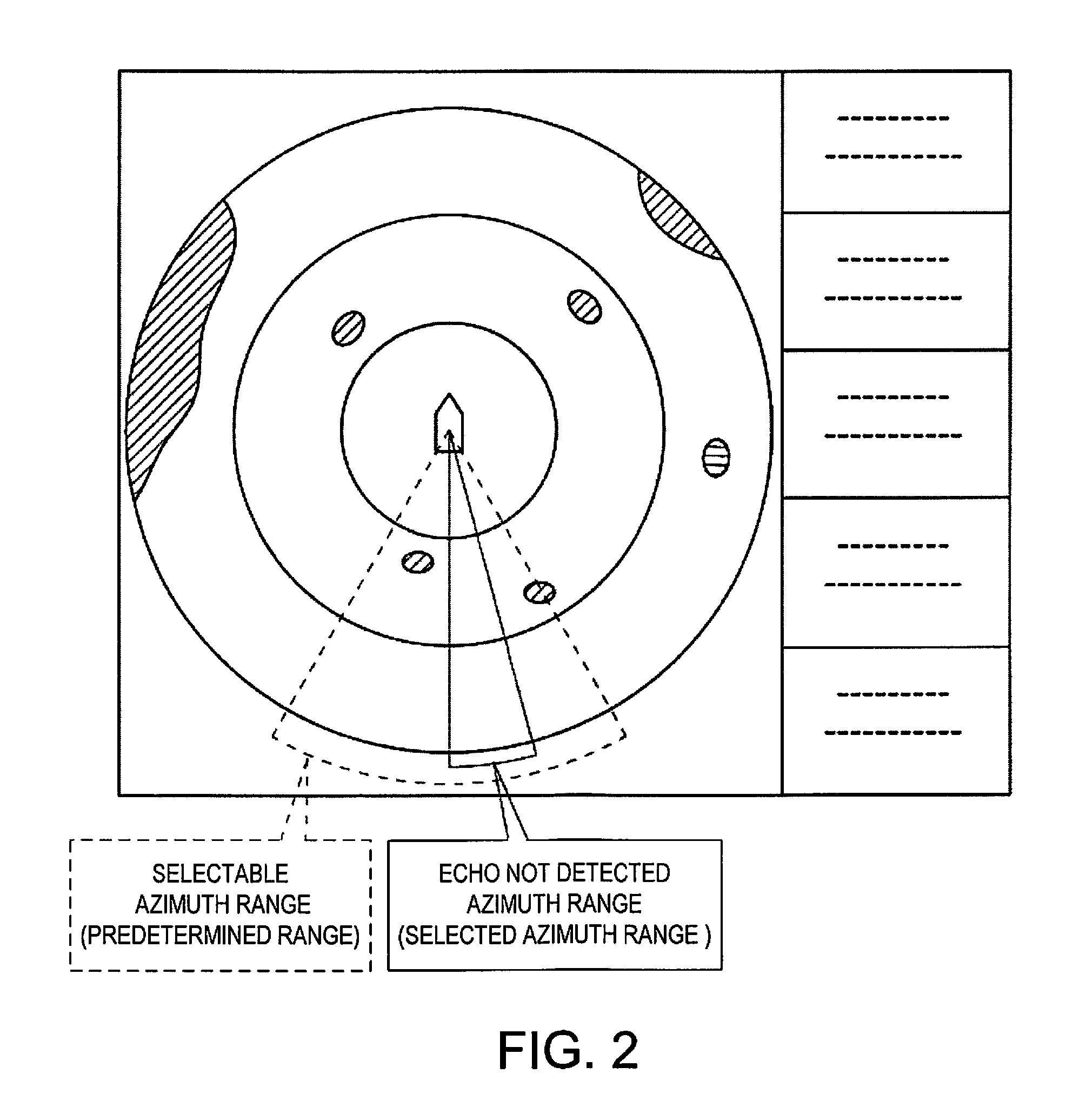
[0041]Next, one embodiment of the present invention is described with reference to the accompanying drawings. FIG. 1 is a block diagram illustrating a configuration of a radar apparatus according to this embodiment of the present invention. FIG. 2 is a view illustrating an image displayed on a display unit in a normal mode.

[0042]The radar apparatus 1 of this embodiment is installed in a ship (hereinafter, may be referred to as “the ship concerned” or simply as “the ship) and detects a position of a target by transmitting a short-pulse radio wave (radar signal) and analyzing a reflection wave (echo) of the radar signal. The radar apparatus 1 includes a radar unit 10 for transceiving the radar signal, a PM unit 20 (radar performance monitor) for measuring performance of the radar unit 10, a PM measuring module 30, and a display unit 40. Note that the term “target” as used herein refers to any objects or lives that are detectable by the radar apparatus 1.

[0043]The radar unit 10 include...


PUM


Abstract

A radar apparatus is provided. The radar apparatus includes a transmitter configured to transmit radar signals via a radar antenna, a receiver configured to receive reflection waves that are echoes of the radar signals, via the radar antenna, a radar image generating module configured to generate a radar image based on the reflection waves received by the receiver, a performance monitor configured to measure performance of at least one of the transmitter and the receiver, and a controller configured to cause the performance monitor to perform the measurement while the transmission of the radar signals is suspended.

Description

CROSS-REFERENCE TO RELATED APPLICATION(S)[0001]This application claims priority under 35 U.S.C. §119 to Japanese Patent Application No. 2013-115568, which was filed on May 31, 2013, the entire disclosure of which is hereby incorporated by reference.TECHNICAL FIELD[0002]The present invention generally relates to a radar apparatus, which is provided with a radar performance monitor for measuring performance of a transmitter and a receiver of the radar apparatus.BACKGROUND OF THE INVENTION[0003]Transmitters (e.g., magnetrons) and receivers (e.g., electronic components of reception circuits) provided in radar apparatuses may deteriorate as being used, or be damaged by a strong signal received externally. Thus, there has been a case where a radar performance monitor is provided to such a radar apparatus in order to check if the transmission intensity and the reception sensitivity of the radar apparatus are good.[0004]This kind of radar apparatus generally includes a radar unit and a PM u...

Claims


Application Information

Patent Timeline
Patent Type & Authority Patents(United States)
IPC IPC(8): G01S7/40G01S13/93G01S13/937
CPCG01S7/4008G01S7/4021G01S13/9307G01S7/40G01S13/89G01S13/937
Inventor YANAGI, KATSUYUKIOHNISHI, YOSHIFUMI
Owner FURUNO ELECTRIC CO LTD
Why Eureka
Try Eureka