Eureka AIR delivers breakthrough ideas for toughest innovation challenges, trusted by R&D personnel around the world.

Remote sensing of remaining battery capacity using on-battery circuitry

Active Publication Date: 2017-01-24
DURACELL U S OPERATIONS INC
View PDF34 Cites 23 Cited by
  • Summary
  • Abstract
  • Description
  • Claims
  • Application Information

AI Technical Summary

Benefits of technology

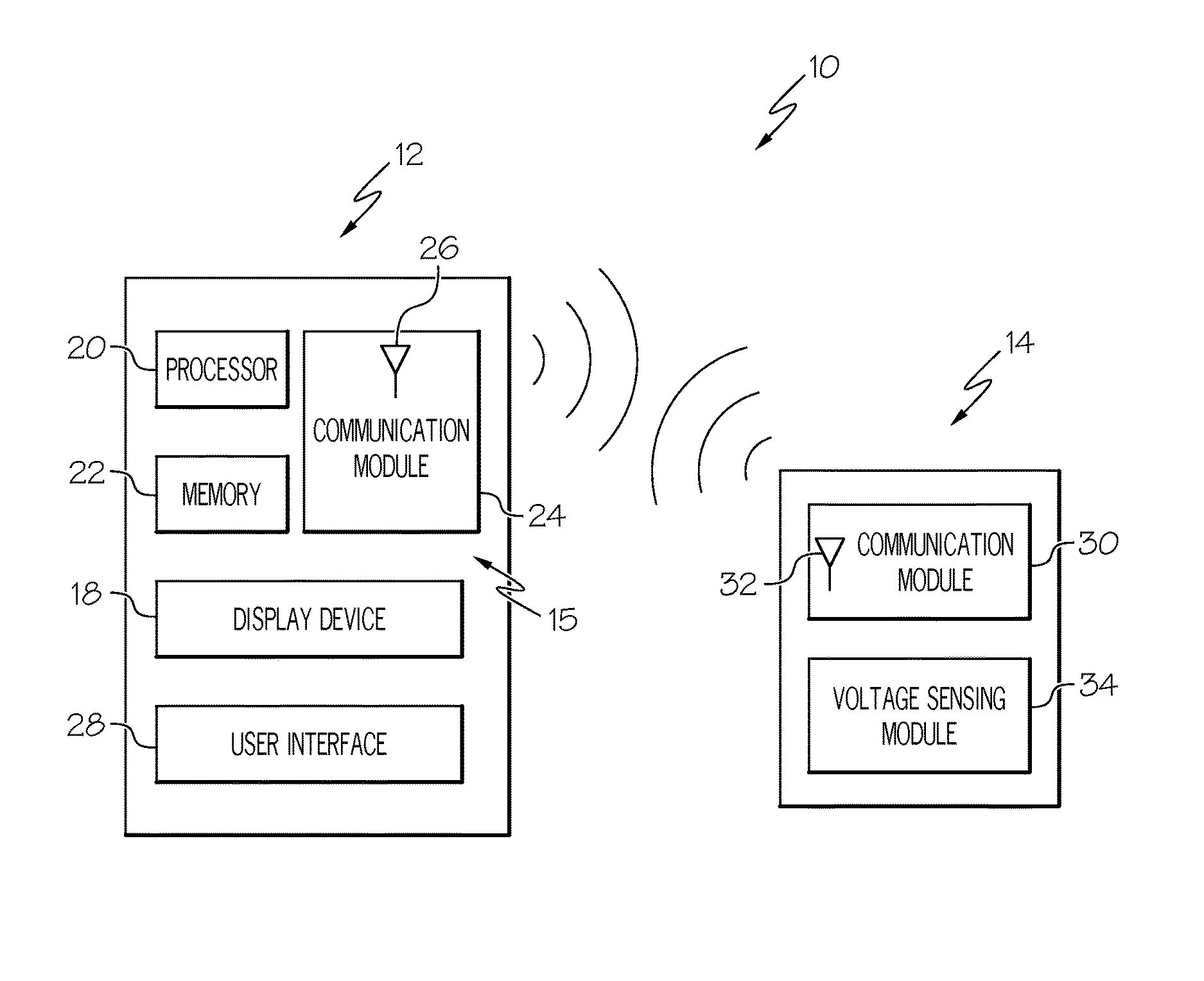
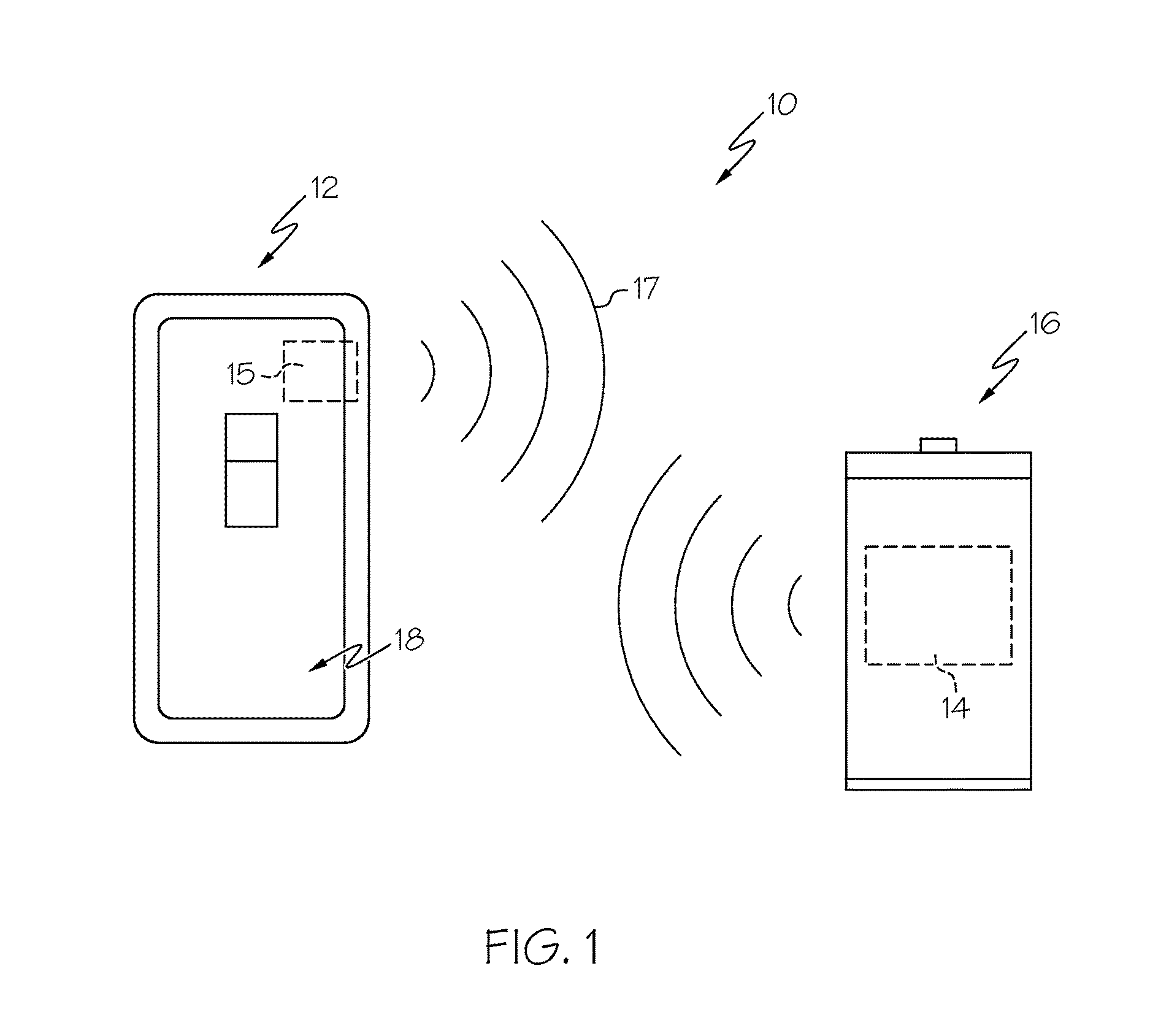
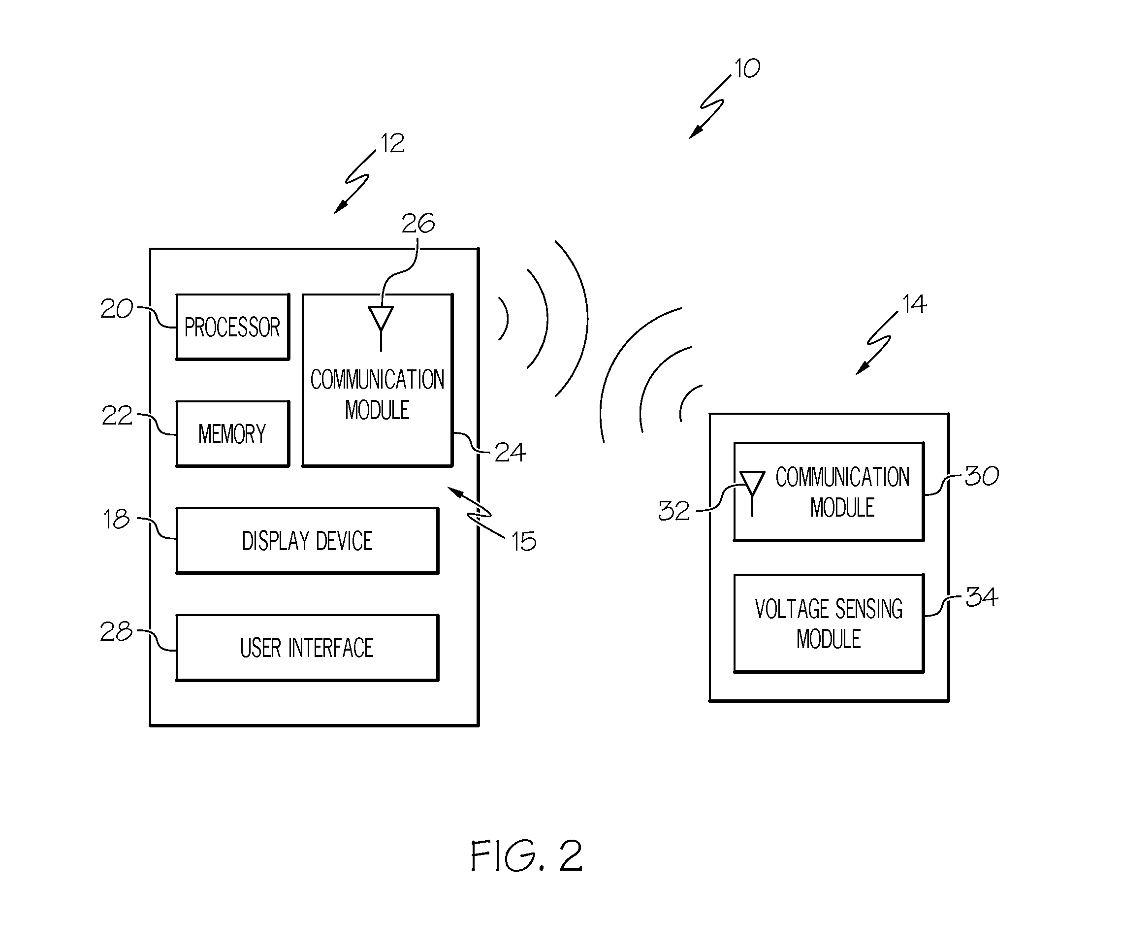
[0005]In another embodiment, a method of remote sensing remaining battery capacity of a battery is provided. The method includes charging or discharging a capacitor of an RC circuit operatively connected to the battery to a predetermined threshold voltage. A response signal is provided using a communications module on the battery to a handheld computing device comprising a reader system once the capacitor reaches the predetermined threshold voltage. A battery voltage is determined using an amount of time taken for the capacitor to charge or discharge to the predetermined threshold voltage using a processor. Remaining battery capacity information is determined using the battery voltage. The remaining battery capacity information is displayed using a display device of the handheld computing device.

Problems solved by technology

However, it is typically necessary to manually hold the battery and / or remove the battery from the device in order to test the battery using thermochromic battery testers.

Method used


Image

  • Remote sensing of remaining battery capacity using on-battery circuitry
  • Remote sensing of remaining battery capacity using on-battery circuitry
  • Remote sensing of remaining battery capacity using on-battery circuitry

Examples


Embodiment Construction

[0018]The following text sets forth a broad description of numerous different embodiments. The description is to be construed as exemplary only and does not describe every possible embodiment since describing every possible embodiment would be impractical, if not impossible, and it will be understood that any feature, characteristic, component, composition, ingredient, product, step or methodology described herein can be deleted, combined with or substituted for, in whole or part, any other feature, characteristic, component, composition, ingredient, product, step or methodology described herein. Numerous alternative embodiments could be implemented, using either current technology or technology developed after the filing date of this patent, which would still fall within the scope of the claims.

[0019]It should also be understood that, unless a term is expressly defined in this specification using the sentence “As used herein, the term ‘——————’ is hereby defined to mean . . . ” or a...


PUM

PropertyMeasurementUnit
microwave frequencyaaaaaaaaaa
voltageaaaaaaaaaa

Abstract

A method of remote sensing a charge includes charging or discharging a capacitor of an RC circuit to a predetermined threshold voltage using a power source. A response signal is provided from a communications module to a handheld computing device comprising a reader system once the capacitor reaches the predetermined threshold voltage. An amount of time taken for the handheld computing device to receive the response signal is determined using a processor. The processor determines charge information using the amount of time.

Description

FIELD OF THE INVENTION[0001]The present invention is generally directed to systems and methods for remote sensing of remaining battery capacity using on-battery circuitry.BACKGROUND OF THE INVENTION[0002]An exemplary type of a common battery tester that is placed on batteries is known as a thermochromic-type tester. In a thermochromic battery tester, there can be a circuit that is connected by a consumer manually depressing one or two button switches. Once the switch is depressed, the consumer has connected the battery to the thermochromic tester. The thermochromic tester may include a resistor—flat silver layer that has a variable width so that the electrical resistance also varies along its length. As current travels through the silver resistor, the dissipated power generates heat that changes the color of a thermochromic ink display that is over the silver resistor. The thermochromic ink display is arranged as a gauge to indicate the relative capacity of the battery. However, it ...

Claims


Application Information

Patent Timeline
Patent Type & Authority Patents(United States)
IPC IPC(8): G01R31/36G01N27/416
CPCG01R31/3627G01R31/3637G01R31/3689G01R31/362G01R31/3606G01R31/388G01R31/371G01R31/382G01R31/3835G01R31/385
Inventor BOURILKOV, JORDAN TODOROVCORONADO HORTAL, SERGIOSPECHT, STEVEN JEFFREY
Owner DURACELL U S OPERATIONS INC
Why Eureka
Eureka Blog
Learn More