Rotary damper

a damper and rotor technology, applied in the direction of shock absorbers, mechanical equipment, transportation and packaging, etc., can solve the problem of general limitation of additional measures

Active Publication Date: 2017-01-10
AUDI AG
View PDF54 Cites 0 Cited by
  • Summary
  • Abstract
  • Description
  • Claims
  • Application Information

AI Technical Summary

Benefits of technology

[0019]The rotary damper can be constructed as hydraulic rotary damper with at least one hydraulic damper element or as electric rotary damper with at least one electric damper element. In the former case, the damping effect of the damper element is based on the circulation of a fluid, such as for example a suitable hydraulic oil or the like, which is received in a volume of the damper element. In the latter case, the damper element is capable to convert mechanical energy into electric energy. The rotary damper includes in this configuration a generator operated by the mass movement and having a stationary stator, a rotor rotatable in relation thereto, and, advantageously, a gear mechanism coupled with the generator. The operating principle of the electric damper is based on the coupling of the generator with the gear mechanism, with the output element of the gear mechanism transmitting to the rotor a rotary movement initiated by the lever element that is directly coupled with the drive element of the gear mechanism. The rotary movement introduced into the rotor causes damping via the generator and the recovery or conversion of the mechanical damper energy, initially resulting from the mass movement, into current generated on the generator side.

Problems solved by technology

Additional measures are generally limited by the known tight space constraints within a wheel well that receives a respective rotary damper.

Method used


Image

  • Rotary damper
  • Rotary damper
  • Rotary damper

Examples


Embodiment Construction

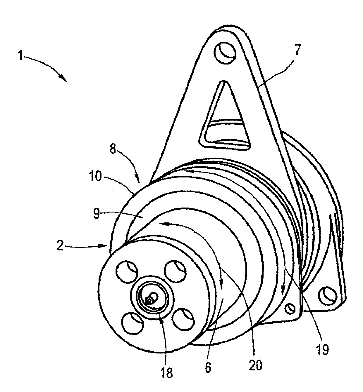
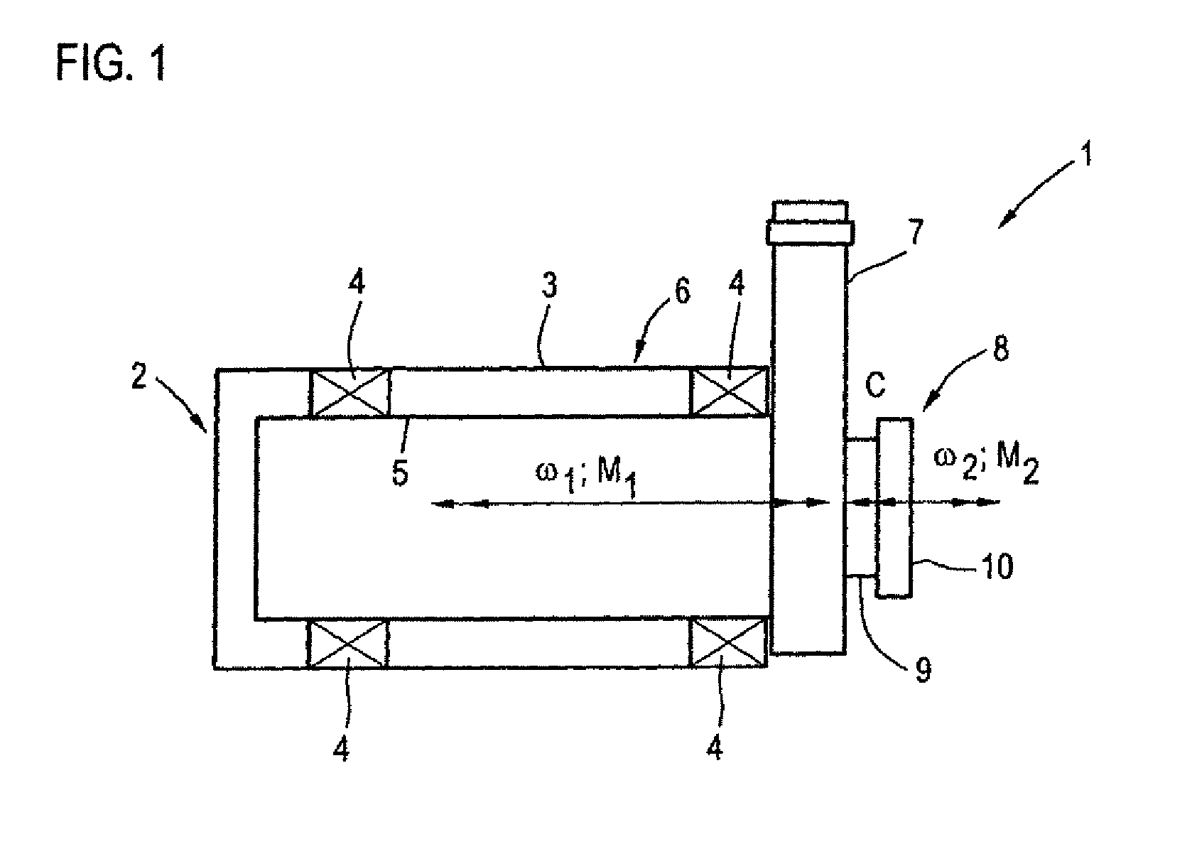
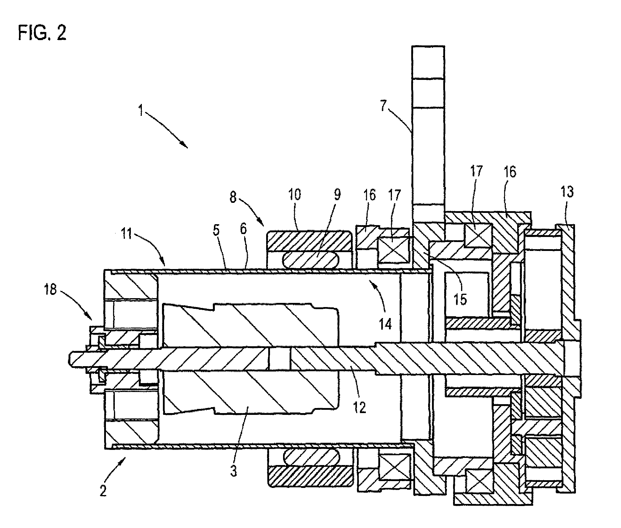
[0025]FIG. 1 shows a basic illustration of a rotary damper 1 according to a first exemplary embodiment by way of a sectional view. The rotary damper 1 is installed within a wheel well of a motor vehicle (not shown) and includes a damper element 2 for damping the relative movement between a first mass, disposed on the wheel-suspension side, and a second mass, disposed on the vehicle-body side. The damping element 2 may be designed, for example, as an electric or hydraulic damper.

[0026]The damping element 2 has a fixed first damper part 3 and a second damper part 5 mounted rotatably relative thereto via bearing elements 4 to generate a damping force. The first damper part 3 may also serve as housing 6 of the damper element 2. The housing 6 and the damper parts 3, 5 have each a hollow-cylindrical shape. The second damper part 5 is connected via a lever element 7 (articulated lever) which can be moved or pivoted by the mass movement and is connected to the first mass. The lever element ...


PUM


Abstract

A rotary damper for a motor vehicle includes at least one damper element for damping the relative movement of a first mass located on the wheel-suspension side and of a second mass located on the vehicle-body side, with at least one vibration absorber (8) being arranged on the rotary damper (1).

Description

CROSS-REFERENCES TO RELATED APPLICATIONS[0001]This application is the U.S. National Stage of International Application No. PCT / EP2012 / 002007, filed May 10, 2012, which designated the United States and has been published as International Publication No. WO 2012 / 156047 and which claims the priority of German Patent Application, Serial No. 10 2011 101 701.5, filed May 17, 2011, pursuant to 35 U.S.C. 119(a)-(d).BACKGROUND OF THE INVENTION[0002]The invention relates to a rotary damper for a motor vehicle, including at least one damper element for damping the relative movement between a first mass, arranged on the side of a wheel suspension, and a second mass, arranged on a side of the vehicle body.[0003]Many areas of technology require damping of relative movements between two components of a vibratory mechanical system. One example involves vibration damping on a motor vehicle body in the region of the suspension of the body on the chassis. Hydraulic dampers, such as in the form of line...

Claims


Application Information

Patent Timeline
Patent Type & Authority Patents(United States)
IPC IPC(8): F16F13/00F16F9/00B60G17/02B60G15/06B60G11/23F16F9/12F16F13/06B60G13/16B60G13/18F16F9/14F16F15/03F16F15/14
CPCF16F13/06B60G11/23B60G13/16B60G13/18B60G15/06B60G17/025F16F9/12F16F9/145F16F15/03F16F15/1442B60G2202/1424B60G2202/22B60G2202/30B60G2202/42B60G2202/442B60G2204/419B60G2204/4191F16F7/108F16F7/116F16F9/14
Inventor WILLEMS, MARCO
Owner AUDI AG
Why Eureka
Try Eureka