
Systems, devices and methods for treating pelvic floor disorders

a technology of pelvic floor and system, applied in the field of systems, devices and methods for treating pelvic floor disorders, can solve the problems of increasing intra-abdominal pressure, exacerbate female urinary incontinence, urine leakage out of the urethra during stressful activity, etc., and achieve the effect of stabilizing the pelvic region and promoting tissue growth

Active Publication Date: 2017-01-10
BOSTON SCI SCIMED INC
View PDF11 Cites 0 Cited by
  • Summary
  • Abstract
  • Description
  • Claims
  • Application Information

AI Technical Summary

Benefits of technology

The invention is about devices and methods for delivering surgical implants to patients. The devices include a delivery device with a curved region that can be used to implant a supportive mesh in the pelvic region for pelvic floor repair and urinary incontinence treatment. The devices can be used to deliver various types of surgical implants and can be associated with other devices for assisting in the surgery. The methods include securing the implants to the patient's body and delivering them to the desired location. The invention aims to provide improved surgical procedures for delivering implants and promoting tissue growth within the pelvic region.

Problems solved by technology

Moreover, pelvic floor disorders often cause or exacerbate female urinary incontinence (UI).
In ISD, the urinary sphincter valve, located within the urethra, fails to close (or “coapt”) properly, causing urine to leak out of the urethra during stressful activity.
In hypermobility, the pelvic floor is distended, weakened, or damaged, resulting in increases in intra-abdominal pressure (e.g., due to sneezing, coughing, straining, etc.) and consequently the bladder neck and proximal urethra rotate and descend.
As a result, the urethra does not close with sufficient response time, and urine leaks through the urethra.
Often, treatments of stress incontinence are made without treating the pelvic floor disorders at all, potentially leading to an early recurrence of the pelvic floor disorder.
However, these devices may be difficult for a surgeon to manipulate within the posterior pelvic region without adversely affecting surrounding anatomical structures during the delivery process.
Moreover, when treating pelvic floor disorders and UI it is desirable to anchor the sling to a plurality of locations in the pelvic region, but most commonly available surgical kits do not provide devices that are suitably sized and / or shaped.
Thus, surgeons have limited ability to access different locations in the pelvic region.

Method used


Image

  • Systems, devices and methods for treating pelvic floor disorders
  • Systems, devices and methods for treating pelvic floor disorders
  • Systems, devices and methods for treating pelvic floor disorders

Examples


embodiment 101

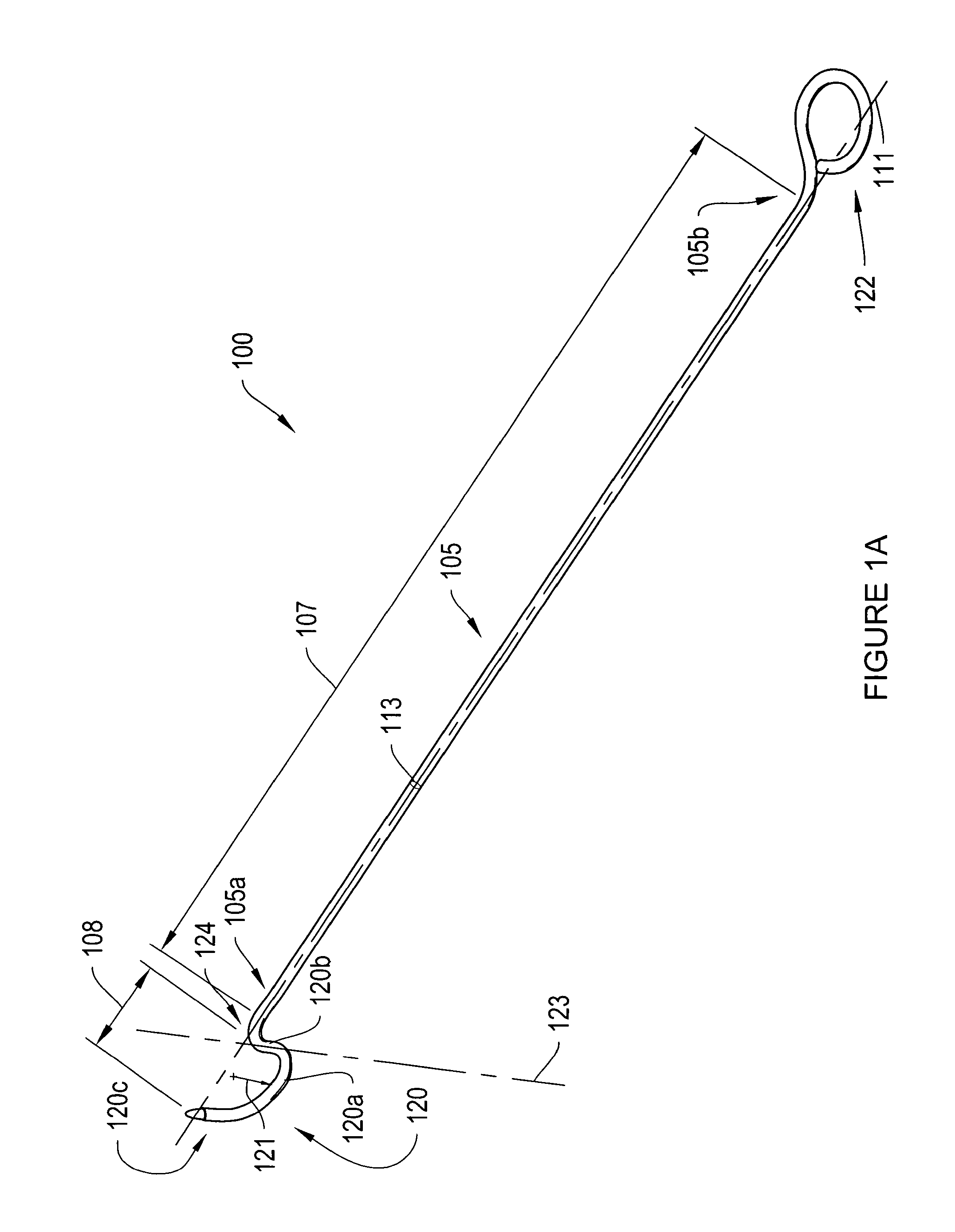
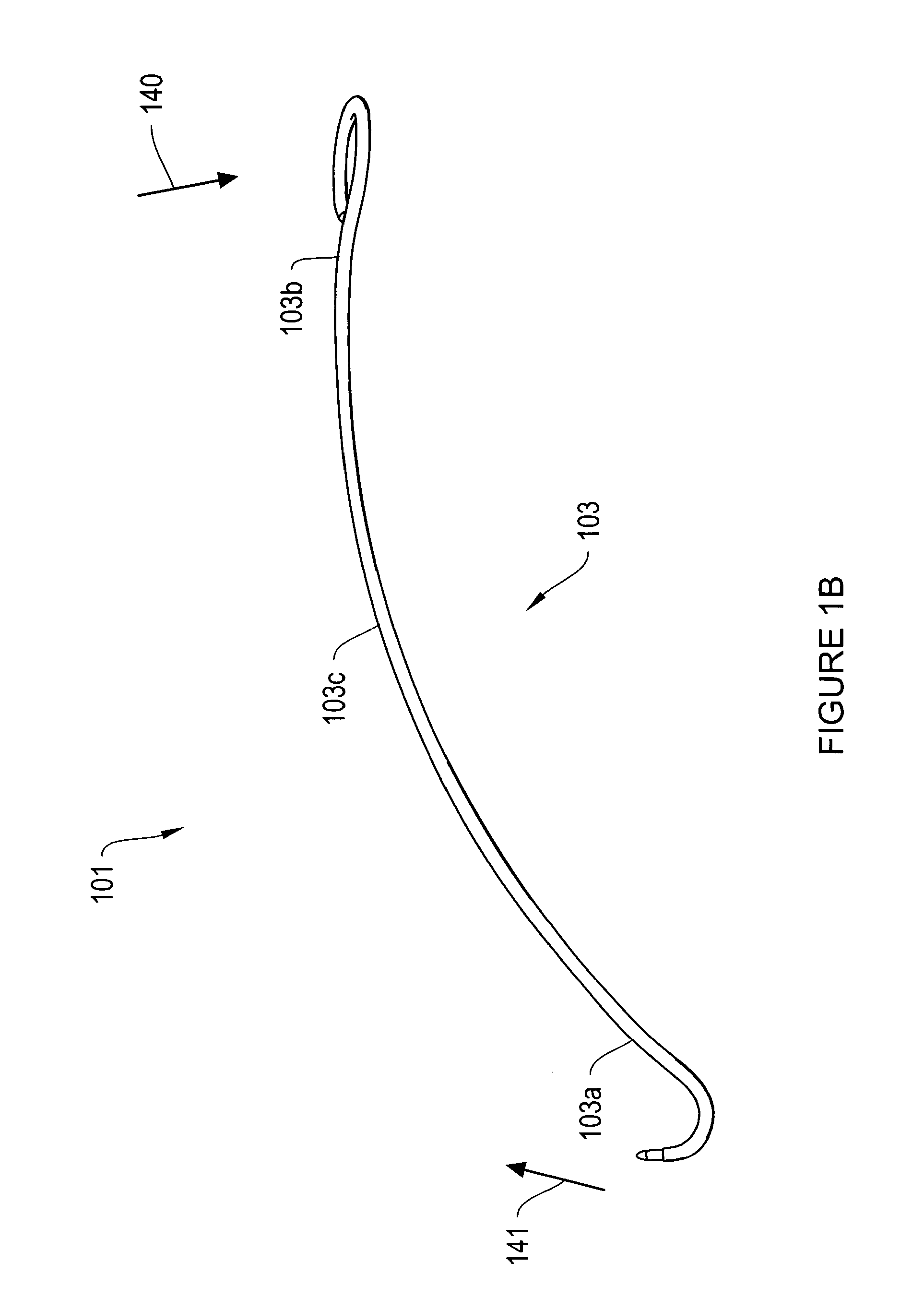
[0042]The shaft 105 is shown to be substantially linear, but it may be slightly curved to form either a convex or a concave arc to further facilitate delivery of the head. FIG. 1B illustrates an alternate embodiment 101 of the delivery device 100 of FIG. 1A having a curved shaft 103 instead of the linear shaft 105 of FIG. 1A. The curved shaft 103 may facilitate passage of the device through the vaginal canal to access the sacrospinous ligament or coccygeus muscle of the patient. In addition, the curved shaft allows rotation of the delivery device 101 for insertion of the head 120 into the patient's tissues. This may be done, for example, by applying a force in direction 140 to the proximal end 103b of the device 101 thereby rotating the device about the middle area 103c of the shaft 103 such that the distal end 103a of the shaft 103 and the head 120 rotate into the tissues in the direction 141. The amount of curvature will typically be chosen to facilitate delivery of the device int...

embodiment 300

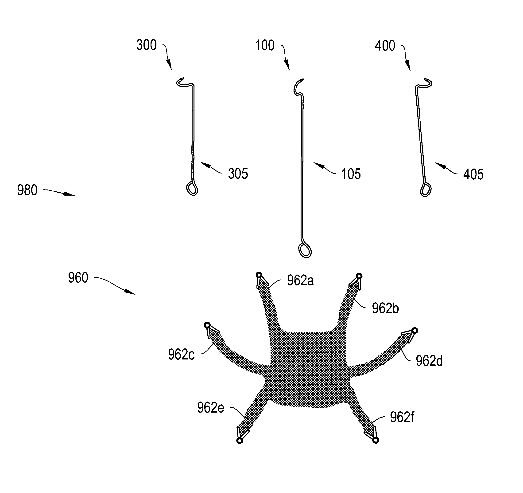
[0050]FIG. 3 shows an alternative embodiment 300 of the device of FIG. 1A having a head 320 oriented perpendicularly to the shaft 305 to allow the operator to deliver a surgical implant to a region of a patient's levator ani muscle, such as the tendinous arch of the levator ani or the iliococcygeus muscle, through a vaginal incision. The levator ani muscle is a broad, thin muscle situated generally on the side of the pelvis that is attached to the inner surface of the lesser pelvis. It is a convenient location to anchor mesh straps in order to provide lateral and / or posterior support and tension for a surgical implant. The iliococcygeus is a portion of the levator ani muscle originating from the ischial spine and the arcus tendineus levator ani and sloping inferiorly toward the midline. The iliococcygeus includes fibers that blend with the longitudinal muscle of the rectum.

[0051]As shown, the delivery device 300 is similar to the device 100, but its head 320 is positioned about 90 d...

embodiment 400

[0052]FIG. 4 shows an alternative embodiment 400 of the device 100 of FIG. 1a having a head 420 oriented on the contra lateral side of its shaft 405 compared to the head 320 and shaft 305 of FIG. 3. The device 400 is then suited to deliver a surgical implant, such as a pelvic floor mesh strap, to a region of a patient's levator ani muscle contra-lateral to the region of the levator ani muscle discussed with respect to FIG. 3. More particularly, the delivery device 400 is similar to the device 100, but with the head 420 rotated by about 90 degrees counterclockwise 450 with respect to the operator of the device. Generally, the head 420 of the device 400 lies substantially in a plane, and the longitudinal axis 411 of the shaft 405 is normal to the plane. The head 420 traces a clockwise 460 path from the linear region 420b to the tip 430, with respect to a distally-looking vantage of the delivery device (i.e., with respect to an operator's vantage). This configuration allows the operato...


PUM


Abstract

Disclosed are implants for pelvic floor repair and related uses, and devices, kits, and methods which can be used to deliver the implants. In certain embodiments, the devices are used to deliver extensions of a surgical implant to respective target tissue regions of the levator ani muscle and the sacrospinous ligament.

Description

RELATED APPLICATIONS[0001]This application is a divisional of U.S. application Ser. No. 11 / 906,969, filed Oct. 3, 2007, the entire contents of which are incorporated by reference herein.BACKGROUND[0002]Pelvic floor disorders afflict many women. According to some studies, about 1 out of 11 women needs surgery for a pelvic floor disorder during her lifetime. The pelvic floor generally includes muscles, ligaments, and tissues that collectively act to support anatomical structures of the pelvic region, including the uterus, the rectum, the bladder, and the vagina. Pelvic floor disorders include vaginal prolapse, vaginal hernia, cystocele, rectocele, and enterocele. Such disorders are characterized in that the muscles, ligaments and / or tissues are damaged, stretched, or otherwise weakened, which causes the pelvic anatomical structures to fall or shift and protrude into each other or other anatomical structures.[0003]Moreover, pelvic floor disorders often cause or exacerbate female urinar...

Claims


Application Information

Patent Timeline
IPC IPC(8): A61F2/00A61B17/06A61B17/00A61B17/29
CPCA61F2/0045A61B17/06066A61B17/06109A61B2017/00805A61B2017/06042A61B2017/06076A61B2017/06085A61B2017/2927A61B2017/00424
Inventor CHU, MICHAEL S. H.
Owner BOSTON SCI SCIMED INC
Learn More