
System and method for evaluating wind flow fields using remote sensing devices

a remote sensing device and wind flow field technology, applied in the field of remote sensing systems, can solve the problems of increasing the fatigue load of downstream turbines, increasing the complexity of interfarm flow and their effects, and uncertainty in optimizing wind farm design and layout, so as to improve the optimization of wind farm layout and operations, accurate evaluation of wind flow upstream and downstream, and refine the design of control systems

Active Publication Date: 2016-12-13
TEXAS TECH UNIV SYST
View PDF14 Cites 9 Cited by
  • Summary
  • Abstract
  • Description
  • Claims
  • Application Information

AI Technical Summary

Benefits of technology

This patent describes a system and method to better understand and optimize the flow of wind in wind farms. It uses special radar technology to evaluate the structure of the wind caused by turbines. This information is important for designing better wind farms and reducing energy costs. The patent also notes that other types of remote sensing technology can be used instead of radar. Overall, the patent aims to improve the accuracy and efficiency of wind energy utilization.

Problems solved by technology

Additionally, enhanced turbulence contained within wakes can create increased fatigue loading on downstream turbines [5-7].
Poor understanding of the modulated flows through wind farms leads to uncertainty in optimizing wind farm design and layout [11-12].
As wind farms grow to include more turbines both onshore and offshore, these inter-farm flows and their effects become more complex.
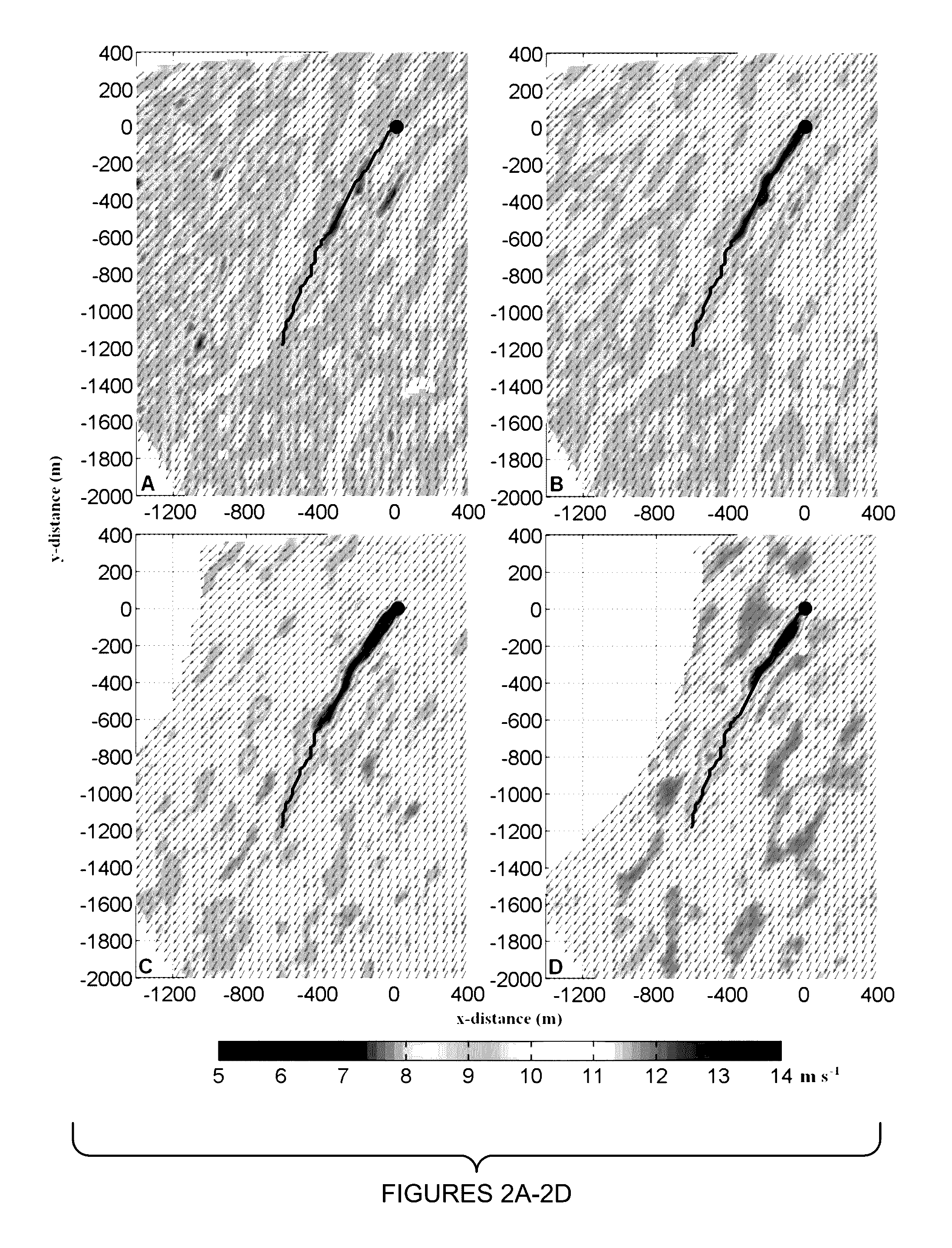
Full-scale observations of the flow through a wind farm are exceedingly limited in quantity and spatial coverage.

Method used


Image

  • System and method for evaluating wind flow fields using remote sensing devices
  • System and method for evaluating wind flow fields using remote sensing devices
  • System and method for evaluating wind flow fields using remote sensing devices

Examples


Embodiment Construction

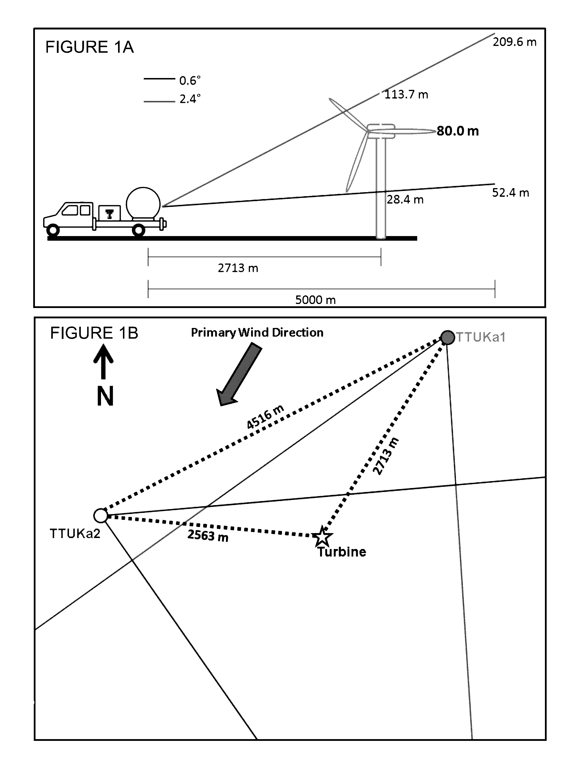
[0060]While the making and using of various embodiments of the present invention are discussed in detail below, it should be appreciated that the present invention provides many applicable inventive concepts that can be embodied in a wide variety of specific contexts. The specific embodiments discussed herein are merely illustrative of specific ways to make and use the invention and do not delimit the scope of the invention. The discussion herein relates primarily to wind flows in the vicinity of wind farms, but it will be understood that the concepts of the present invention are applicable to evaluating wind flows in and around other areas of interest. Moreover, the discussion relates to examples using mobile Doppler radar units, but it will be understood that the concepts of the present invention are applicable to other types of radar, other types of remote sensing technologies (e.g., LIDAR) and other technologies developed in the future (fixed, mobile or both).

[0061]The present i...


PUM


Abstract

The present invention provides a system and method for obtaining data to determine one or more characteristics of a wind field using a first remote sensing device and a second remote sensing device. Coordinated data is collected from the first and second remote sensing devices and analyzed to determine the one or more characteristics of the wind field. The first remote sensing device is positioned to have a portion of the wind field within a first scanning sector of the first remote sensing device. The second remote sensing device is positioned to have the portion of the wind field disposed within a second scanning sector of the second remote sensing device.

Description

PRIORITY CLAIM AND CROSS-REFERENCE TO RELATED APPLICATIONS[0001]This application claims priority to U.S. Provisional Patent Application Ser. No. 61 / 676,394, filed on Jul. 27, 2012 and U.S. Provisional Patent Application Ser. No. 61 / 683,022, filed on Aug. 14, 2012, the entire contents of which are incorporated herein by reference.[0002]This application is related to U.S. patent application Ser. No. 13 / 952,611 filed on Jul. 27, 2013, PCT Patent Application No. PCT / US2013 / 052435 filed on Jul. 27, 2013, and PCT Patent Application No. PCT / US2013 / 052434 filed on Jul. 27, 2013.STATEMENT OF FEDERALLY FUNDED RESEARCH[0003]This invention was made with government support under Grant No. DE-FG-06-G086092 awarded by the United States Department of Energy Congressionally Directed Project: Great Plains Wind Power Test Facility. The government has certain rights in the invention.FIELD OF THE INVENTION[0004]The present invention relates generally to the field of remote sensing systems and, more part...

Claims


Application Information

Patent Timeline
Patent Type & Authority Patents(United States)
IPC IPC(8): G01S13/95G01S13/87G01S13/58G01P5/00
CPCG01S13/95G01P5/001G01S13/589G01S13/87G01S13/951G01S13/956F03D17/00F05B2270/32F05B2270/321Y02A90/10
Inventor SCHROEDER, JOHNHIRTH, BRIANGUYNES, JERRY
Owner TEXAS TECH UNIV SYST
Learn More