
Inflatable foot cushion

a foot cushion and inflatable technology, applied in the field of inflatable foot cushion, can solve the problems of increasing the occurrence of pressure ulcers of the heel, and achieve the effects of reducing the left and right lateral rotation of the ankle, reducing the occurrence of pressure ulcers, and improving the protection of the achilles' tendon area

Active Publication Date: 2016-12-13
EHOB
View PDF4 Cites 2 Cited by
  • Summary
  • Abstract
  • Description
  • Claims
  • Application Information

AI Technical Summary

Benefits of technology

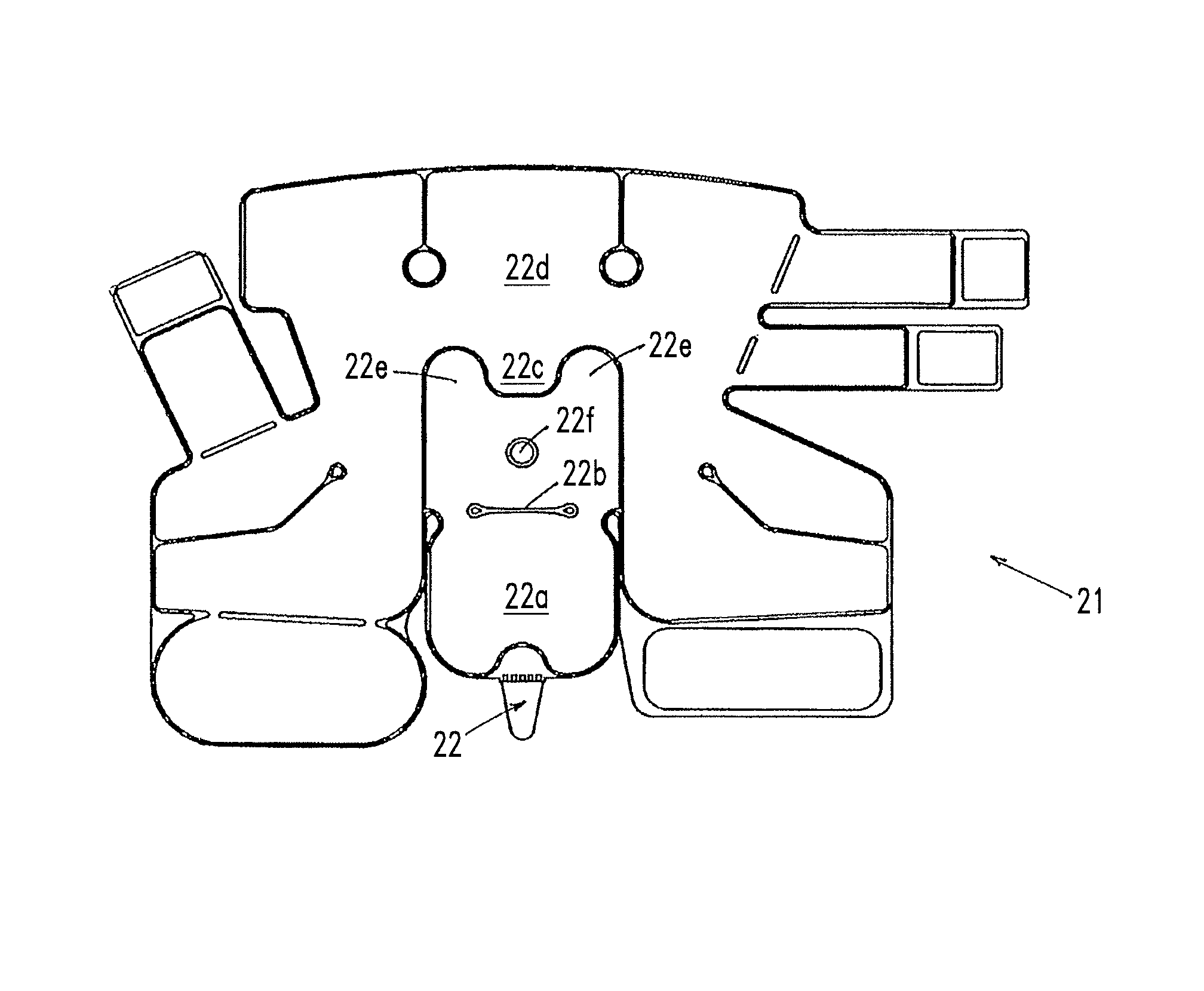
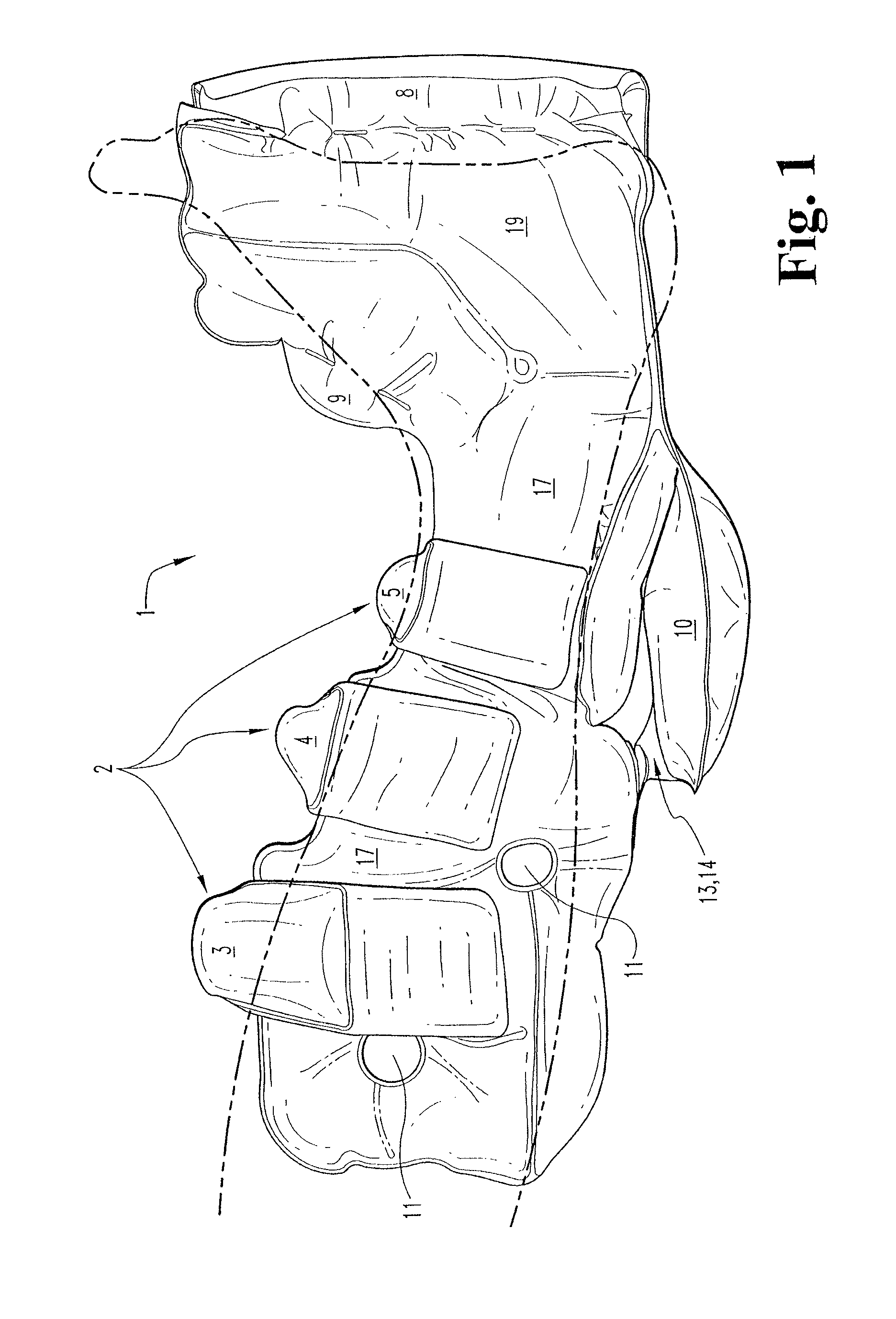
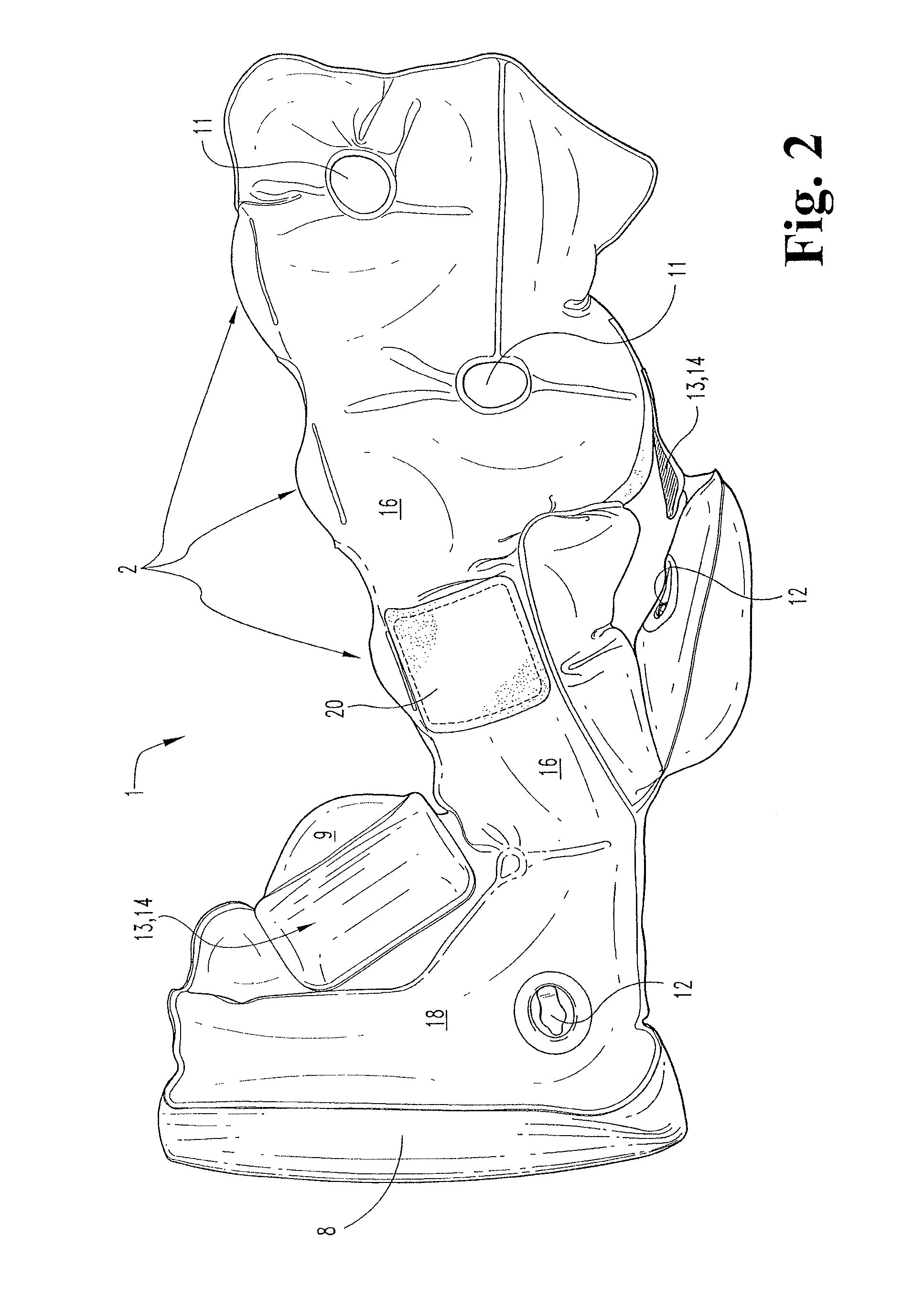
[0007]The present invention are further improvements to the inflatable foot cushion of pending U.S. patent application Ser. No. 13 / 432,068, and to the Inflatable Foot Cushion of U.S. Pat. No. 5,328,445, which are both incorporated herein by reference in their entireties. The novel improvements of the present invention relate to the independent inflatable chamber (10) of pending U.S. patent application Ser. No. 13 / 432,068, and to the inflatable cushion (16) of U.S. Pat. No. 5,328,445, which improvements provide better protection of the Achilles' tendon areas of patients who wear the improved inflatable foot cushion (21) of the present invention (see FIG. 9); provide for better unloading of pressures on the heels of patients; that provide for reduced left and right lateral rotations of the ankles of patients; and that provide for less stress on the materials of construction upon rotation of the improved inflatable chamber (22a) under the improved inflatable foot cushion (21) of the present invention.
[0008]One embodiment of the improved inflatable foot cushion of the present invention to reduce the force amplifications upon the heel of a foot received therein when the body is in a supine position is the improvement comprising means for increasing the volume of the inflatable chamber of the inflatable foot cushion that pivotally swings under the inflatable foot cushion to provide increased support for the inflatable foot cushion when it is placed upon a substrate.
[0009]Another embodiment of the improved inflatable foot cushion of the present invention to reduce the force amplifications upon the heel of a foot received therein when the body is in a supine position is the further improvement comprising means to improve the pivotal axis about which the larger volume inflatable chamber is pivotally swung under the inflatable foot cushion of the present invention to reduce the bunching of the construction material.
[0010]Another embodiment of the improved inflatable foot cushion of the present invention to reduce the force amplifications upon the heel of a foot received therein when the body is in a supine position is the further improvement comprising means to increase the volume of the main chamber of the inflatable foot cushion in the direction of the larger volume inflatable chamber whereby two lateral bladders are created on either side of the main chamber volume expansion and between which the larger volume inflatable chamber is cradled when the larger volume inflatable chamber is pivoted under the inflatable foot cushion which thereby provides improved lateral stability to the inflatable foot cushion.

Problems solved by technology

During the era of using pillows to offload mechanical forces on the heel, the occurrence of pressure ulcers of the heel continued to increase.

Method used


Image

  • Inflatable foot cushion
  • Inflatable foot cushion
  • Inflatable foot cushion

Examples


Embodiment Construction

[0020]Referring now to FIG. 8, which is an exploded top plan view of the inflatable foot cushion (1) of U.S. patent application Ser. No. 13 / 432,068, FIG. 8 illustrates the relationships of the novel constituent parts of that inflatable foot cushion, and which also illustrates how two pliable plastic sheets have been joined together by conventional means to form the novel inflatable chambers and straps of the inflatable foot cushion (1) of U.S. patent application Ser. No. 13 / 432,068.

[0021]Referring to FIG. 2, there is one inflation port (12) for all of the air inflatable chambers shown in FIG. 8, all of which are in fluid communication with each other, with one exception. FIG. 2 also illustrates an inflation port (12) for independent air inflatable chamber (10), which is not in fluid communication with the other cambers illustrated in FIG. 8, and which is of the same size and has the same functionality as does independent air inflatable cushion (16) of the Inflatable Foot Cushion of ...


PUM


Abstract

Medical advantages are provided by the novel improvements made to the inflatable foot cushion of the present invention to the inflatable foot cushion of U.S. patent application Ser. No. 13 / 432,068 and the Inflatable Foot Cushion of U.S. Pat. No. 5,328,445, including better protection of a patient's Achilles' tendon areas; better unloading of the pressures on the patient's heels due to the increased elevation of the patient's heels above substrates; and the prevention of left and right lateral rotation of the ankles of patients wearing the novel inflatable foot cushion of the present invention by its two novel lateral cushions formed by expanding the main chamber of the improved inflatable foot cushion of the present invention there between, which novel lateral cushions cradle and stabilize the improved inflatable chamber of the present invention when it is pivoted under the improved inflatable foot cushion of the present invention.

Description

CROSS-REFERENCE TO RELATED APPLICATIONS[0001]The present application claims priority to U.S. Provisional Patent Application Ser. No. 61 / 748,561, filed Jan. 3, 2013, and is a continuation-in-part of U.S. patent application Ser. No. 13 / 432,068.BACKGROUND OF THE INVENTION[0002]The present invention relates generally to the field of inflatable devices for supporting the human body, and more particularly is concerned with a novel improved inflatable foot cushion to counter the force amplifications experienced by the foot, and particularly the heel area of the foot, when the body is in the supine position.[0003]In the supine position, the foot assumes the shape of a wedge that tapers from the toes down to the heel. The mechanical force amplifications that are typically associated with a wedge are therefore also experienced by the wedge-shaped foot. The heel area, and more specifically the points of contact between the heel area and the substrate upon which the body is lying in the supine ...

Claims


Application Information

Patent Timeline
Patent Type & Authority Patents(United States)
IPC IPC(8): A61F5/01A61F5/058A61H9/00
CPCA61F5/0195A61F5/012A61F5/05816A61F2005/0183A61H9/0092A61H2201/1697A61H2205/106
Inventor SPAHN, JAMES G.CONWAY, BRIAN D.LAUGHLIN, DAVID P.ROGERS, SCOTT D.
Owner EHOB
Learn More