Eureka AIR delivers breakthrough ideas for toughest innovation challenges, trusted by R&D personnel around the world.

In-flight kite deflation and control systems

a kite and control system technology, applied in special-purpose vessels, marine propulsion, vessel construction, etc., can solve the problems of kite losing its aerodynamic shape and deflating the bladder, and achieve the effect of reducing the aerodynamic shape of the kite and the ability to power-up in the wind

Active Publication Date: 2016-12-06
OCEAN RODEO SPORTS
View PDF22 Cites 5 Cited by
  • Summary
  • Abstract
  • Description
  • Claims
  • Application Information

AI Technical Summary

Benefits of technology

[0024]The invention provides a safety system for use with kites in kite boarding on water, over snow or on land, to allow the kite rider to quickly and easily de-pressurize and deflate the kite's leading edge bladder totally or partially, thereby reducing the kite's aerodynamic shape and ability to power-up in the wind.
[0033]In scenarios where the kite rider is overpowered or loses control of the kite on the water due to wind gusts, waves, entanglement in the lines of another kite rider, grounding on a shoal or sandbar, wrapping the lines around limbs, wrapping lines around the control bar or falls into the water, or losing his / her board while being dragged along on the water surface, the kite rider could quickly activate the deflation control line.
[0034]Additionally, it is much safer to approach and rescue a kite rider in the water attached to a deflated kite, than to rescue a kite rider attached to an inflated kite that risks suddenly powering up, with the kite lines entangling the kite rider or rescue personnel. Recovering a free-floating deflated kite would be easier and safer than recovering an inflated kite dragging lines and a control bar.
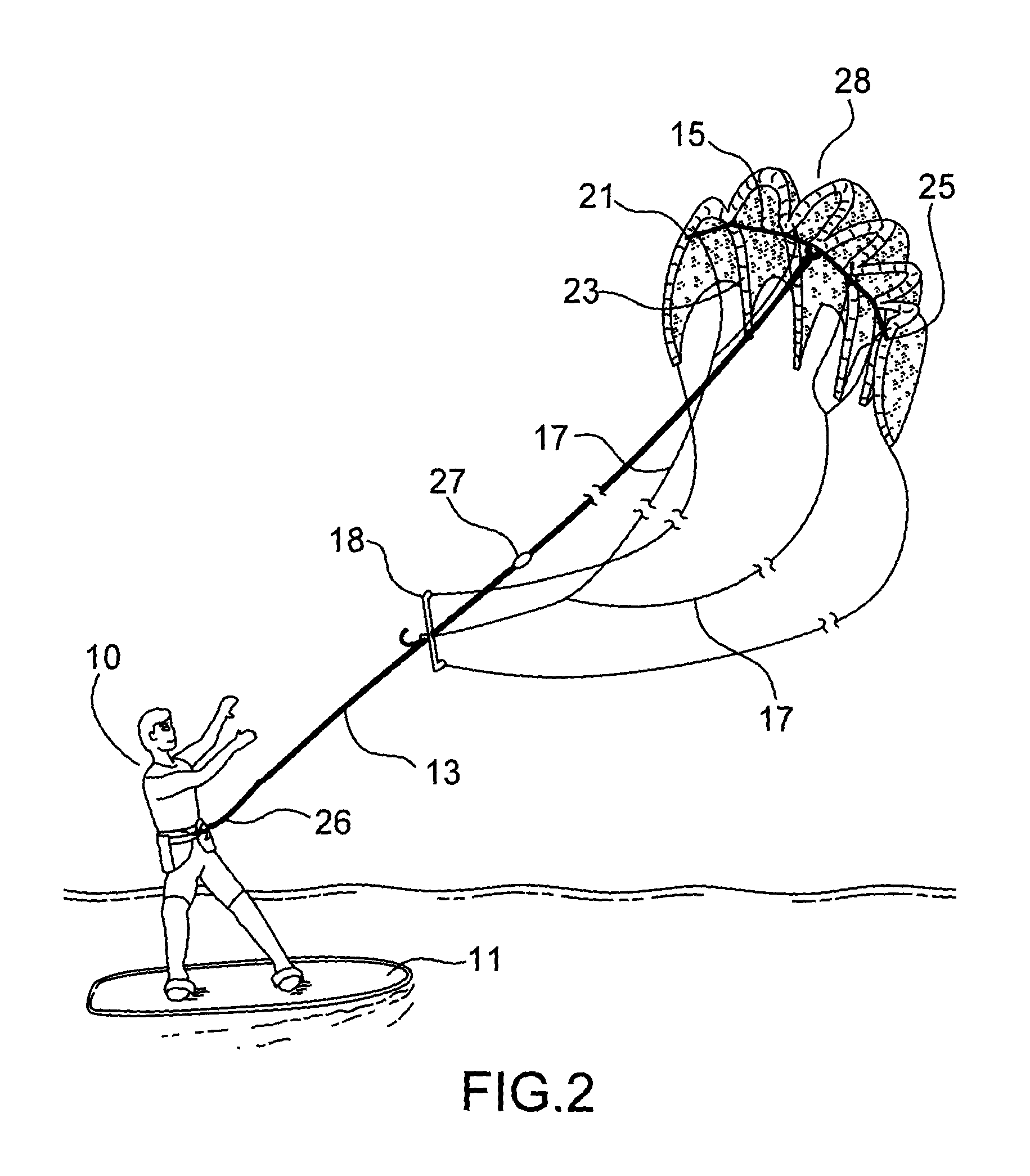
[0037]In another aspect of the invention, tensioning the deflation control line also acts to draw portions of the kite wing (the wing being the portion of the kite that engages the wind when inflated) in toward one another, thereby reducing the footprint of the wing. The deflation control line may include a length of line extending from a point (such as a ring) near the middle of the wing to opposite ends of the wing, such that pulling the deflation control line away from the wing pulls the wing tips in toward the middle thereby collapsing the wing. The smaller deflated-wing footprint reduces the wing's ability to flap and flutter about in the wind, which risks re-powering the kite, albeit to a minor extent. By reducing the footprint of the deflated wing in the water, it is also more convenient for the now-swimming kite rider to gather and control the wing for swimming to shore. According to an aspect of the invention, the length of line may also comprise uni-directional catches to prevent the collapsed wing from inadvertently unfurling, once pulled into a smaller footprint.
[0057]After relieving tension on the tether line, the tether line may remain connected to a leash attached to the harness.
[0061]In another aspect, the invention comprises a method for a rider of a kite board to rapidly depower a kite wing. The kite wing has an inflated leading edge bladder, it is tethered to a harness worn by the rider by means of at least one tether line and the kite wing is connected by outside steering lines to a control bar held by the. The method comprises the steps of releasing said control bar and disengaging a chicken loop connecting the tether line to the harness whereby to cause the wing to tension a deflation control line secured to the harness and attached to a valve on the bladder, causing the valve to open and allowing the bladder to deflate.

Problems solved by technology

Preferably, the valve is responsive to tension along the deflation control line such that tensioning the line causes the valve on the bladder to open, deflating the bladder and causing the kite to lose its aerodynamic shape.

Method used


Image

  • In-flight kite deflation and control systems
  • In-flight kite deflation and control systems
  • In-flight kite deflation and control systems

Examples


Embodiment Construction

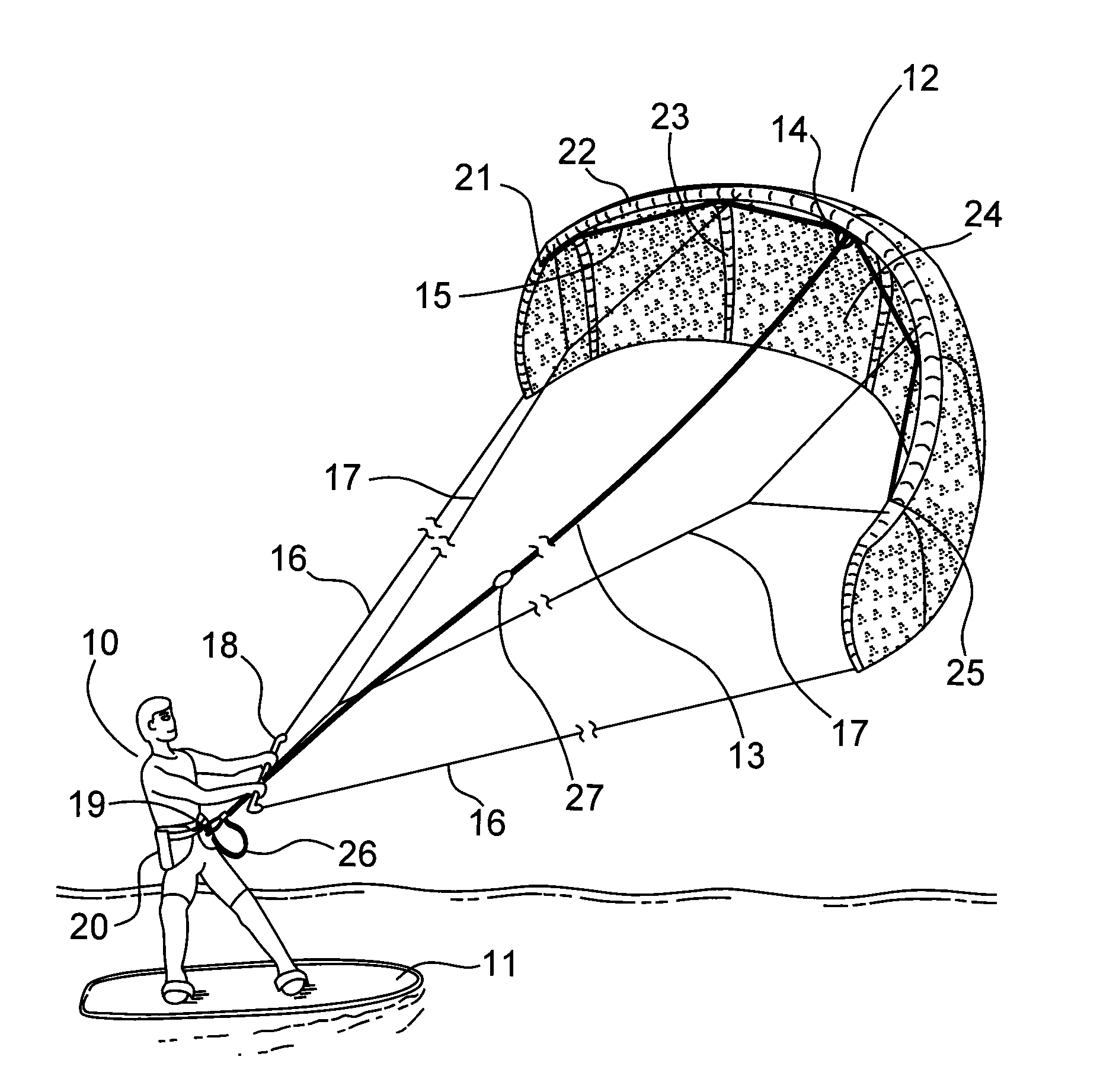
[0095]FIG. 1 is a sketch of the preferred embodiment with the kite rider 10 standing on a kite board 11 holding a kite 12, with the deflation control line 13 threaded through a hole in control bar 18 and connected to leash 26, one end of which is connected to the kite rider's harness 20.

[0096]The other end of deflation control line 13 branches into two lines 15 at ring 14 (see FIG. 3), with each of these lines 15 connecting to the wing's opposed tips at points 21 and 25. Lines 15 are also engaged to the wing by being threaded through a number of loop attachment points positioned along the wing's leading edge, for example by loops 34 (see FIG. 4).

[0097]The wing's leading edge bladder is depicted as 22 in FIG. 1. Bladder 22 is comprised of an elastomeric material, which is housed in an abrasion resistant cloth covering, such as Dacron polyester. For convenience, the bladder and bladder covering are both depicted as 22.

[0098]In many prior art applications, the leading edge bladder comp...


PUM


Abstract

A massive de-powering system for a kite wing used in kite boarding comprises a deflation control line that connects to a valve on the kite wing's leading edge bladder. In the preferred embodiment, disengaging the tether line from the harness causes the deflation control line to tension and to open the valve, thereby deflating the bladder. Tension along the deflation control line may also act to draw in spaced portions of the wing thereby collapsing it and further reducing the power generated by the wing.

Description

FIELD OF THE INVENTION[0001]The invention relates to a safety system for use in kite sports.BACKGROUND OF THE INVENTION[0002]Kite boarding, sometimes also referred to as kite surfing, is an extreme sport whereby a person uses a kite, generally having a “C” or modified “C” shape. Such shape, also termed “a leading edge inflatable kite”, is created by using a hand or electrically operated pump to inflate an elastomeric bladder contained within a protective cover material forming the kite's leading edge. The kite's leading edge, which forms a rigid C-shaped 4-8 inch diameter round tube when inflated, also has one or more orthogonally aligned abutting struts, which structure supports the fabric material forming the kite canopy. Kites are deflated for packaging and transport. During use, the kite's leading edge and struts are inflated to about 3-8 lbs. above ambient atmospheric pressure. The leading edge bladder and struts can be inflated simultaneously, or separately.[0003]Without infla...

Claims


Application Information

Patent Timeline
Patent Type & Authority Patents(United States)
IPC IPC(8): B63H9/06B64C31/06B63B35/79B62B15/00A63C5/11A63C17/26
CPCB63H9/0685B63B35/7979B64C31/06A63C5/11A63C17/267B62B15/002B62B15/003B63H2009/0692B64C2031/065B63H8/16B63H8/12B63H8/18
Inventor BERRANG, PETER G.HARRINGTON, ROSS D.MYERSCOUGH, RICHARD K.
Owner OCEAN RODEO SPORTS
Why Eureka
Eureka Blog
Learn More