
Implant system for knee prosthesis

a knee prosthesis and implant technology, applied in the field of orthopaedic implants, can solve the problems of implant failure and implant failure, and achieve the effect of reducing hoop stress

Active Publication Date: 2016-11-22
MICROPORT ORTHOPEDICS INC
View PDF5 Cites 1 Cited by
  • Summary
  • Abstract
  • Description
  • Claims
  • Application Information

AI Technical Summary

Benefits of technology

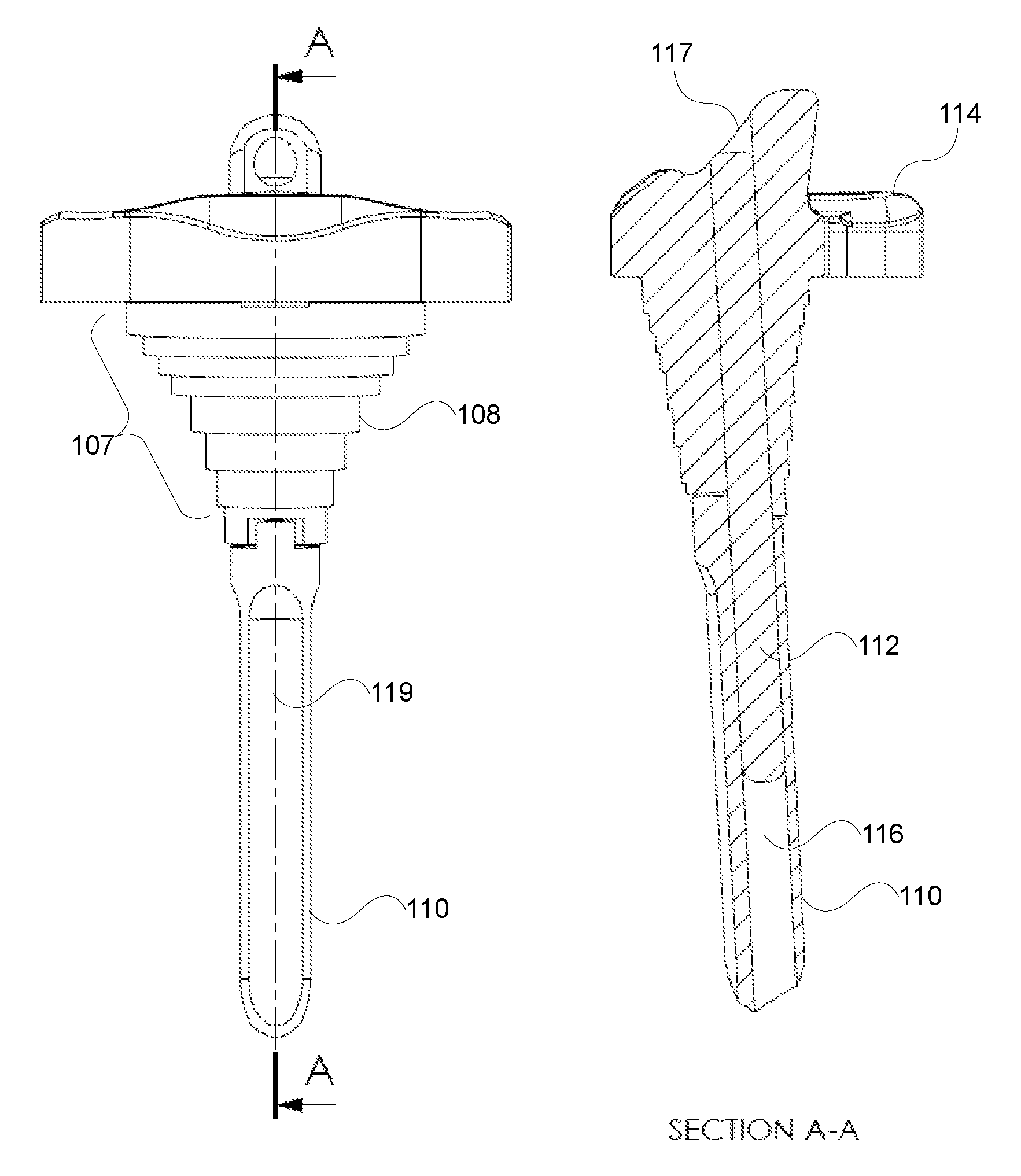
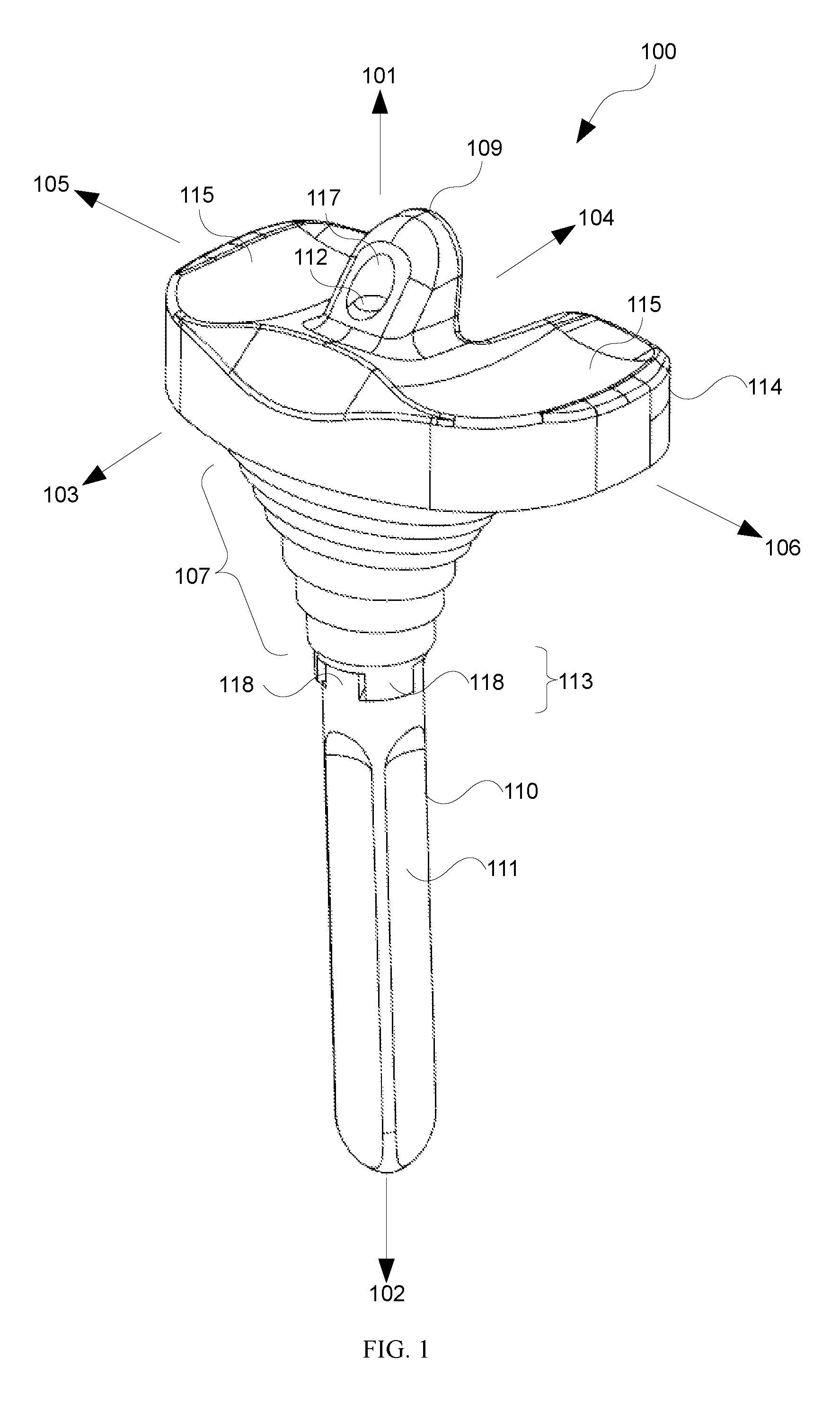
The patent text talks about a device used to reinforce a bone called a tibia. The device has a strengthening rod that is placed inside the bone through a shaft. The strengthening rod is designed to reduce movement in relation to the shaft. This helps to reduce stress on the bone. The patent also mentions a terraced geometry that is used to further reduce stress on the bone.

Problems solved by technology

In some cases, over time, implants may fail for one reason or another.
For example, wear, infection, improper loading of the bone followed by loosening of the implant in the bone are reasons for implant failure.

Method used


Image

  • Implant system for knee prosthesis
  • Implant system for knee prosthesis
  • Implant system for knee prosthesis

Examples


Embodiment Construction

[0035]For the purposes of promoting an understanding of the principles in accordance with the disclosure, reference will now be made to the embodiments illustrated in the drawings and specific language will be used to describe the same. It will nevertheless be understood that no limitation of the scope of the disclosure is thereby intended. Any alterations and further modifications of the inventive features illustrated herein, and any additional applications of the principles of the disclosure as illustrated herein, which would normally occur to one skilled in the relevant art and having possession of this disclosure, are to be considered within the scope of the disclosure.

[0036]Before the structures, systems and associated methods relating to the implant system for knee prosthesis are disclosed and described, it is to be understood that this disclosure is not limited to the particular configurations, process steps, and materials disclosed herein as such configurations, process step...


PUM


Abstract

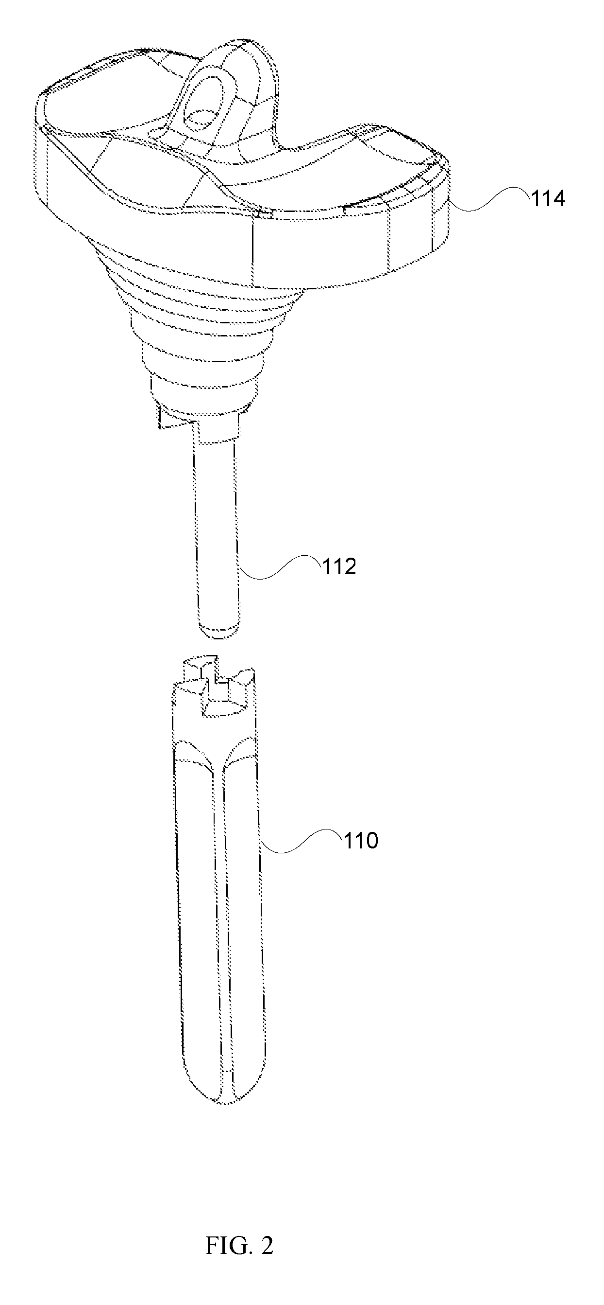
An implant system for knee prosthesis includes a superiorly located femoral bearing block having a femoral component bearing surface and an inferiorly located stem selectively attachable to the bearing block. A strengthening rod is disposed within at least a portion of the femoral bearing block and the stem.

Description

CROSS REFERENCE TO RELATED APPLICATION[0001]This application claims priority to Australian Application No. 2014902890 which was filed on Jul. 25, 2014, the contents of which are incorporated by reference.BACKGROUND[0002]1. Field of the Disclosure[0003]The disclosure relates generally to orthopedic implants, and more particularly, but not necessarily entirely, to an implant system for knee prosthesis and more particularly a cemented system for tibial implant.[0004]The disclosure has been developed primarily for use in tibial implants and will be described hereinafter with reference to this application. However, it will be appreciated that the disclosure is not limited to this particular field of use.[0005]2. Background of the Disclosure[0006]In total knee arthroplasty, the knee joint is replaced with an artificial knee implant.[0007]The knee implant traditionally includes a femoral component and a tibial component. It is common practice to ream a portion of the bone (the distal end o...

Claims


Application Information

Patent Timeline
Patent Type & Authority Patents(United States)
IPC IPC(8): A61F2/38A61F2/30
CPCA61F2/389A61F2/3886A61F2002/30014A61F2002/30365A61F2002/30433A61F2002/30434A61F2002/30593A61F2002/30616A61F2002/30772A61F2002/30897A61F2002/30901A61F2310/00029
Inventor NEVINS, RUSSELL
Owner MICROPORT ORTHOPEDICS INC
Learn More