Optical fiber splicing unit, optical fiber splicing method, and holding member for optical fiber splicing unit

a technology of optical fiber splicing and holding member, which is applied in the direction of optics, instruments, optical light guides, etc., can solve the problems of large installation space in the closure or the like which accommodates optical fiber, the operation is complicated and the manufacturing cost is increased, and the operation is simplified. , the effect of simplifying the joint operation

Active Publication Date: 2016-11-15
FUJIKURA LTD +1
View PDF18 Cites 1 Cited by
  • Summary
  • Abstract
  • Description
  • Claims
  • Application Information

AI Technical Summary

Benefits of technology

[0033]In the optical fiber splicing method according to the second aspect of the present invention, the optical fiber splicing method may further include: in the process of inserting the second optical fiber between the half-split elements of the mechanical splice and butting the tip of the second optical fiber to the tip of the first optical fiber, abutting the second anchoring fixation member, which is fixed to the second optical fiber, to a second spacer restricting advancement of the second anchoring fixation member, stopping the advancement of the second anchoring fixation member with respect to the mechanical splice at a position at which the second optical fiber is to butt to the tip of the first optical fiber, subsequently, gripping and fixing the second optical fiber between the half-split elements by pulling-out the insertion piece from the portion between the half-split elements of the other end portion of the mechanical splice in a state where the butting between the first and second optical fibers is maintained, retracting the second spacer from a position at which the second spacer is capable of abutting the second anchoring fixation member, concurrently with or after the gripping and fixing of the second optical fiber, thereafter, advancing the second anchoring fixation member toward the mechanical splice, and restricting retraction of the second anchoring fixation member with respect to the mechanical splice using an anchoring portion, in a state where a bending is formed in the second optical fiber between the mechanical splice and the second anchoring fixation member.
[0040]Accordingly, by only inserting the second optical fiber between the elements of the mechanical splice, since the second optical fiber can butt the tip of the first optical fiber at a desired position between the elements, the but-joint operation can be simplified.
[0041]Therefore, even when an operation is performed at a dark place or in a narrow operation space, the but-joint operation of the optical fibers can be easily and reliably performed.
[0043]In the present invention, according to the bend formation, it is possible to prevent an excessive tensile force from applying to the optical fiber (the portion which is gripped and fixed between the elements) which is gripped and fixed to the mechanical splice, and the butt-joint state of the optical fibers can be stably maintained.

Problems solved by technology

Moreover, in the splicing method of the optical fibers of the related art which presses the bending generated at both sides of the mechanical splice using a finger and confirms whether or not the uniform bending is realized, in order to obtain the uniform bending, a slightly complicated operation such as adjustment by pressing the bending using a finger is required.
In addition, in the structure in which the optical fiber splicing unit is accommodated in the case body such as the closure or the cabinet and the optical fiber cable is fixed to the case body by the fixing tool provided in the inner portion, there is a problem that a large installation space is required in the closure or the like which accommodate the optical fiber splicing unit.
In addition, there is a problem that since the structure of the closure or the like is complicated, the manufacturing costs are increased.

Method used


Image

  • Optical fiber splicing unit, optical fiber splicing method, and holding member for optical fiber splicing unit
  • Optical fiber splicing unit, optical fiber splicing method, and holding member for optical fiber splicing unit
  • Optical fiber splicing unit, optical fiber splicing method, and holding member for optical fiber splicing unit

Examples


first embodiment

Optical Fiber Splicing Unit

[0120]Hereinafter, a first embodiment of the present invention will be described with reference to the drawings.

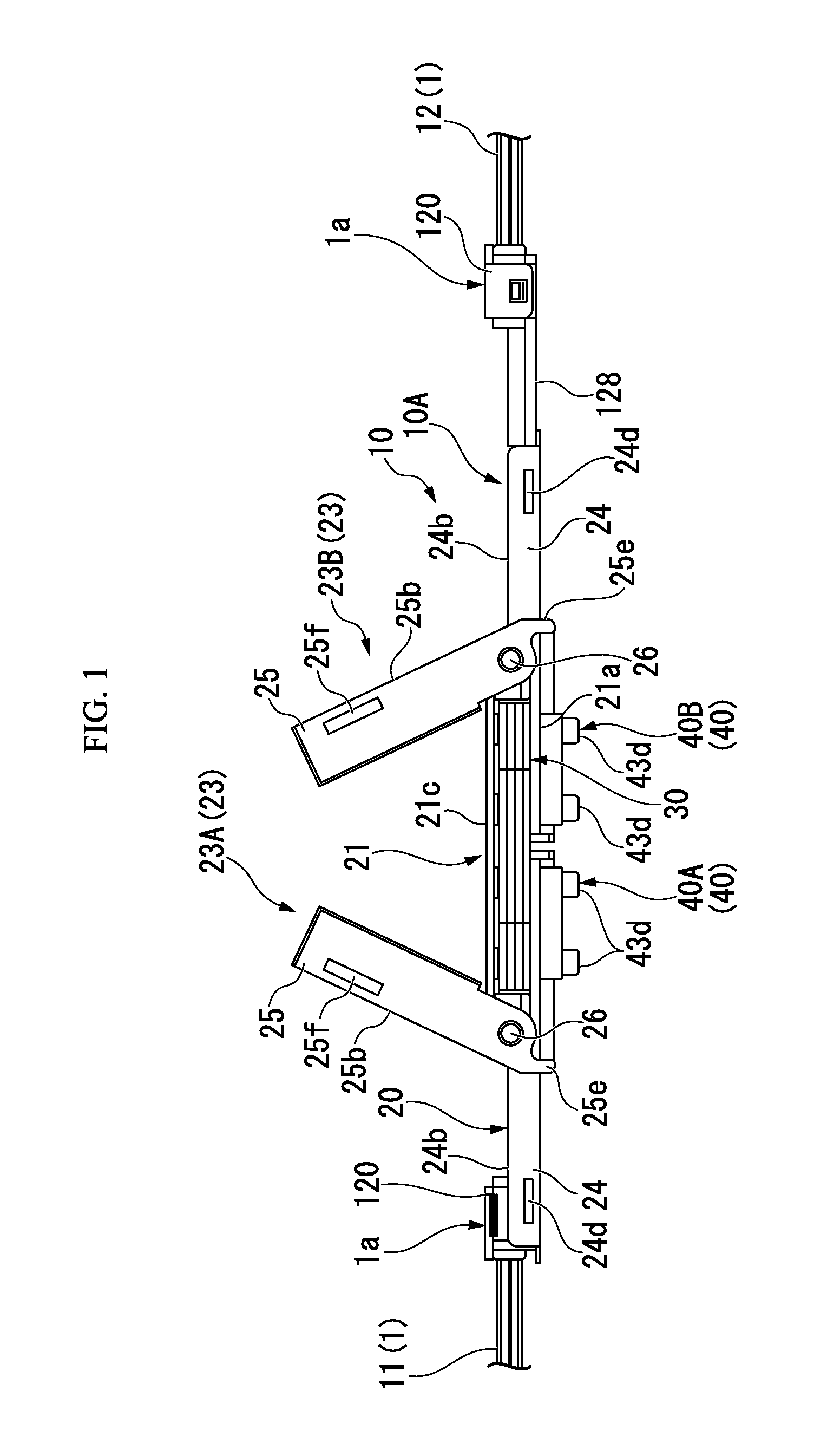
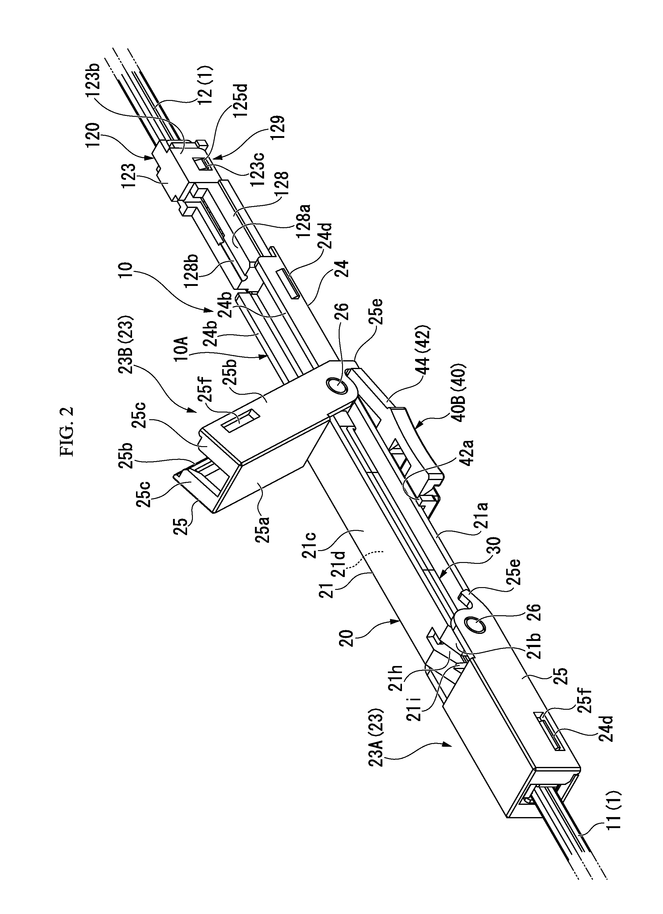
[0121]Moreover, with respect to an optical fiber splicing unit 10, in FIGS. 1, 2, 4, and 5, an upper side is defined as the upper portion, and a lower side is defined as the lower portion.

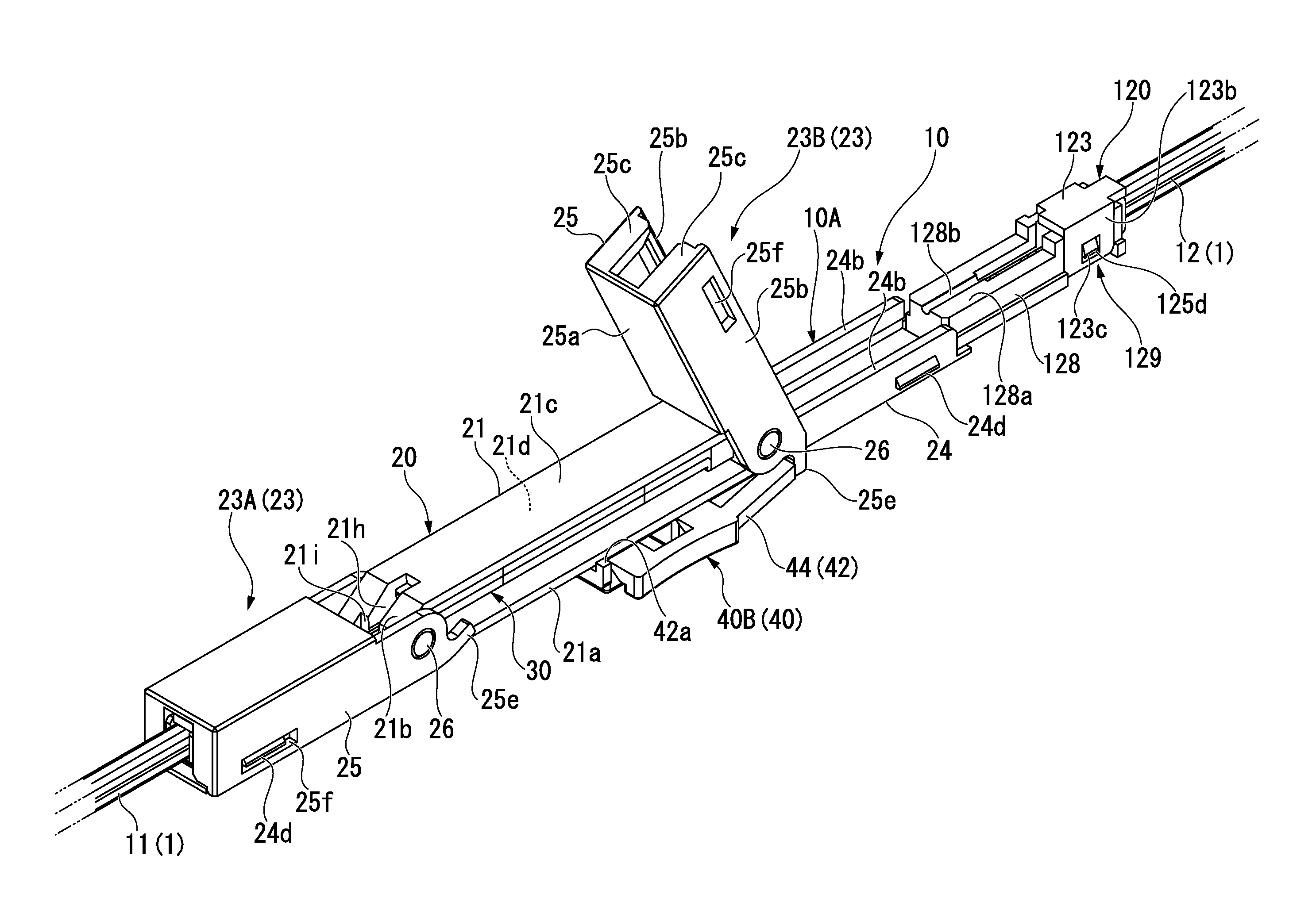
[0122]As shown in FIGS. 1 to 3, the optical fiber splicing unit 10 described here is schematically configured to include a mechanical splice 30 (hereinafter, also referred to as a splice), an elongated unit base 20 having a splice holder portion 21 which holds the splice 30, lever members 25 which are attached to both ends in a longitudinal direction of the unit base 20, and a splice tool 40 which is assembled to the splice 30.

[0123]As shown in FIGS. 1 to 3, the optical fiber splicing unit 10 of the shown example can be applied to a splice (optical splice) between optical fiber cables.

[0124]A reference numeral 11 is assigned to one (first optical fiber cable) of...

second embodiment

[0499]Hereinafter, a second embodiment of the present invention will be described with reference to the drawings.

[0500]First, an outline of the second embodiment according to the present invention will be described with reference to FIGS. 39A to 39F, and thereafter, a more specific embodiment will be described with reference to FIGS. 20, and 22 to 38.

[0501]Moreover, in the present embodiment, the same reference numerals are assigned to the same components as the first embodiment.

[0502]

[0503]An optical fiber splicing method of the present embodiment is a method in which the optical fiber 11a which is drawn from the terminal of the first optical fiber cable 11 to be exposed (protruded) and the optical fiber 12a which is drawn from the terminal of the second optical fiber cable 12 to be exposed (protruded) are but-jointed using the mechanical splice 30, and thus, the optical fiber cables 11 and 12 are spliced to each other.

[0504]The optical fibers 11a and 12a is a coated optical fiber ...

third embodiment

[0689]Hereinafter, a third embodiment of the present invention will be described with reference to the drawings.

[0690]Moreover, in the present embodiment, the same reference numerals are assigned to the same components as the first embodiment.

[0691]As shown in FIG. 40, a holding member 50 for an optical fiber splicing unit holds an optical fiber splicing unit 2010 which can be applied to the splice (optical splice) between the pair of optical fiber cables 1.

[0692]The reference numeral 11 is assigned to one of the optical fiber cables 1 spliced to each other by the optical fiber splicing unit 2010, and the reference numeral 12 is assigned to the other.

[0693]As shown in FIG. 20, the optical fiber cable 1 (optical fiber cables 11 and 12) is configured by collectively coating the sheath 4 made of a synthetic resin so that the optical fiber 2 and the linear tensile strength bodies 3 having flexibility are in parallel with one another.

[0694]As the tensile strength bodies 3, for example, a...


PUM


Abstract

An optical fiber splicing unit includes: a mechanical splice which aligns optical fibers and puts the optical fibers between half-split elements to splice the optical fibers to each other; a splice holder portion which holds the mechanical splice; fixing member guide portions which respectively guide anchoring fixation members that are respectively fixed to the optical fibers at two sides of the held mechanical splice; anchoring portions which respectively anchor the anchoring fixation members, the anchoring fixation members being respectively guided by the fixing member guide portions and advancing; and a first spacer which abuts one anchoring fixation member and is disposed to be retracted to restrict the advancement of said one anchoring fixation member, said one anchoring fixation member being guided by one fixing member guide portion and advancing.

Description

CROSS REFERENCE TO RELATED APPLICATIONS[0001]This application is a continuation application based on a PCT Patent Application No. PCT / JP2012 / 072993, filed Sep. 7, 2012, whose priority is claimed on Japanese Patent Application No. 2011-196353, filed on Sep. 8, 2011, Japanese Patent Application No. 2011-227447, filed on Oct. 14, 2011, Japanese Patent Application No. 2011-227448, filed on Oct. 14, 2011, and Japanese Patent Application No. 2011-251566, filed on Nov. 17, 2011, the entire content of which are hereby incorporated by reference.BACKGROUND OF THE INVENTION[0002]1. Field of the Invention[0003]The present invention relates to an optical fiber splicing unit which can be used to splice optical fibers, an optical fiber splicing method using the same, and a holding member for an optical fiber splicing unit.[0004]2. Description of the Related Art[0005]Japanese Unexamined Patent Application, First Publication No. 2010-26166 discloses an optical fiber splicing unit which includes a me...

Claims


Application Information

Patent Timeline
Patent Type & Authority Patents(United States)
IPC IPC(8): G02B6/36G02B6/38G02B6/255
CPCG02B6/3803G02B6/3802G02B6/3806G02B6/3809
Inventor MORIOKA, HIROYUKIYAMAGUCHI, TAKASHITAKIZAWA, KAZUHIROTAKAMIZAWA, KAZUTOSHIDAIDO, ATSUSHIIDA, MASAHIRO
Owner FUJIKURA LTD
Why Eureka
Try Eureka