
Support of removable components in a teeth model manufactured by means of CAM

a technology of removable components and teeth models, which is applied in the direction of impression caps, instruments, analogue processes for specific applications, etc., can solve the problem of high accuracy requirements for dental restorations

Active Publication Date: 2016-11-15
3SHAPE AS
View PDF17 Cites 1 Cited by
  • Summary
  • Abstract
  • Description
  • Claims
  • Application Information

AI Technical Summary

Benefits of technology

The patent text describes a method for improving the accuracy of a virtual model by adding support and positioning features to a removable component and the cavity wall of a virtual model. These features help to reduce the area of contact between the components when creating a physical model from the virtual model. This can be useful when manufacturing models of the upper and lower jaws, as they can be connected using connector pins to test the occlusion of the patient. The technical effect of this method is to increase the accuracy of the virtual model and improve the manufacturing process of physical models.

Problems solved by technology

Accuracy requirements for the dental restorations are very high otherwise the dental restoration will not be visual appealing, fit onto the teeth, could cause pain or cause infections.
It remains a problem to provide an alternative and more efficient method for generating a virtual model of a set of teeth comprising a tooth which requires a restoration and / or a dental treatment, and for generating a physical model of the set of teeth comprising such a tooth, such that the dental technician can test the dental restorations, e.g. a crown, on the physical model.

Method used


Image

  • Support of removable components in a teeth model manufactured by means of CAM
  • Support of removable components in a teeth model manufactured by means of CAM
  • Support of removable components in a teeth model manufactured by means of CAM

Examples


Embodiment Construction

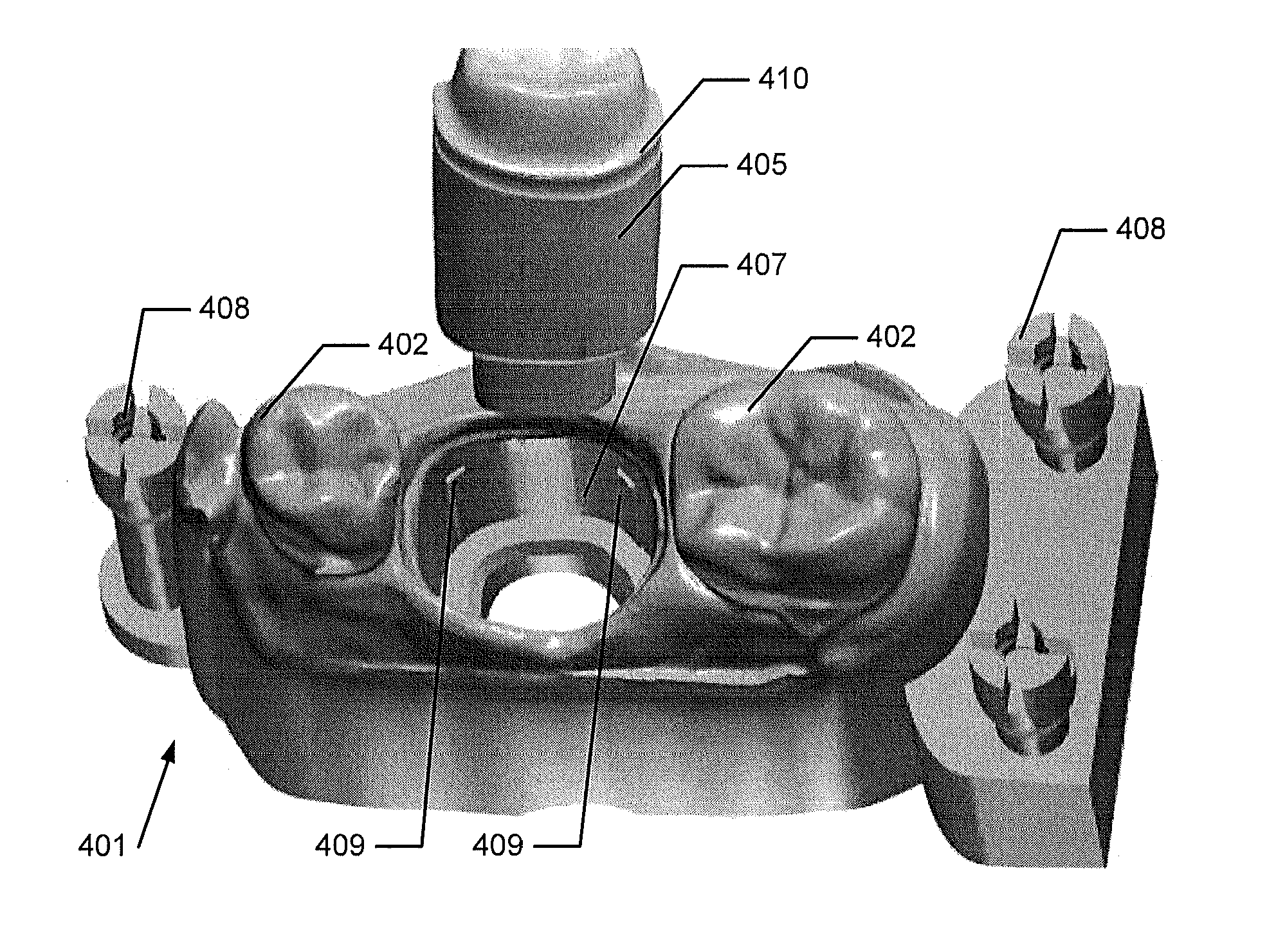
[0277]In the following description, reference is made to the accompanying figures, which show by way of illustration how the invention may be practiced.

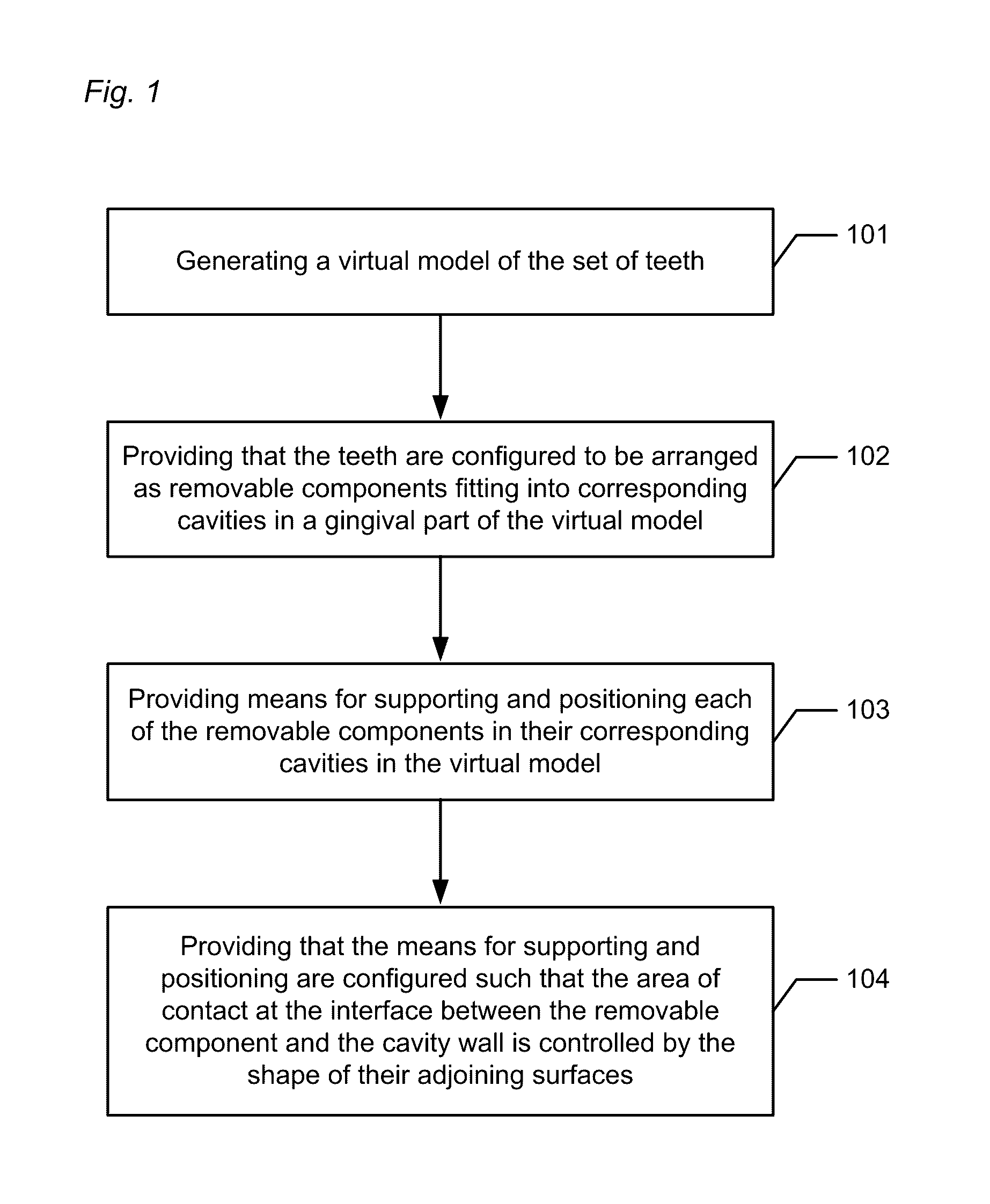
[0278]FIG. 1 shows an example of a flow chart of one embodiment of the method.

[0279]In step 101 a virtual model of a set of teeth is generated, and the virtual model is based on a virtual representation of the set of teeth. The virtual representation may be provided by scanning an impression of the set of teeth or scanning the set of teeth directly in the mouth of the patient using an intraoral scanner. The virtual model may comprise one or more teeth. The virtual model may have been generated previously and the invention is not limited to methods including the generation of the virtual model.

[0280]In step 102 each of the teeth are provided to be configured to be arranged as a removable component in the model, and each removable component is adapted to fit into a corresponding cavity in the gingival part of the model.

[0281]In step 10...


PUM


Abstract

A computer-implemented method of generating a virtual model of a set of teeth for manufacturing a physical model of the set of teeth includes providing a virtual model of the set of teeth generating a cavity in said gingival part, into which cavity a removable component fits, where the removable component and the cavity are configured to provide a gap at an interface; and providing for supporting and positioning the removable component in the cavity, wherein the area of contact between the removable component and the cavity wall at the interface is controlled by the shape of the adjoining surfaces of the supporting and positioning and the other of the removable component and the cavity wall.

Description

BACKGROUND OF THE APPLICATION[0001]This invention generally relates to a computer-implemented method of and a system for generating a virtual model of a set of teeth for manufacturing a physical model of the set of teeth, and to a physical model of a set of teeth.DESCRIPTION OF RELATED ART[0002]When a patient requires a dental restoration, such as crowns, bridges, abutments, or implants, the dentist will prepare the teeth e.g. a damaged tooth is grinded down to make a preparation where a crown can be glued onto. An alternative treatment is to insert implants, such as titanium screws, into the jaw of the patient and mount crowns or bridges on the implants. After preparing the teeth or inserting an implant the dentist can makes an impression of the upper jaw, the lower jaw and a bite registration or a single impression in a double-sided tray, also known as triple trays.[0003]The impressions are sent to the dental technicians who manufacture the restorations. The first step to manufact...

Claims


Application Information

Patent Timeline
IPC IPC(8): G06G7/48G06G7/58A61C13/00A61C13/34A61C9/00G06F17/50
CPCA61C13/0004A61C9/00A61C13/34A61C9/002G06F17/5018G16H50/50A61C19/05B33Y80/00A61C5/77G16H20/40A61C9/0053G06F30/00G06F30/23
Inventor GILLES, BRIEUCFISCHER, DAVIDLANG, MORTEN MARKUSSENFISKER, RUNENONBOE, SVENTOFTHOJ, STEEN FROST
Owner 3SHAPE AS
Learn More