Method of determining an ophthalmic lens

a technology of ophthalmology and lens, applied in the field of determining the ophthalmology lens, can solve the problems of different power correction values and lens obtained by optimisation not perfectly satisfying the wearer, and achieve the effect of better satisfaction for wearers

Active Publication Date: 2016-11-01
ESSILOR INT CIE GEN DOPTIQUE
View PDF2 Cites 2 Cited by
  • Summary
  • Abstract
  • Description
  • Claims
  • Application Information

AI Technical Summary

Problems solved by technology

For presbyopic wearers, the value of the power correction is different for far vision and near vision, because of difficulties of accommodation in conditions of near vision.
This results in the lens obtained by optimisation not perfectly satisfying the wearer.

Method used


Image

  • Method of determining an ophthalmic lens
  • Method of determining an ophthalmic lens
  • Method of determining an ophthalmic lens

Examples


Embodiment Construction

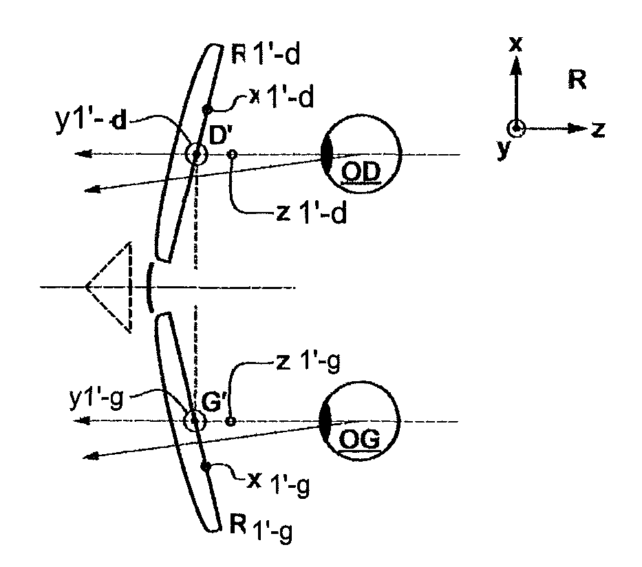
[0072]FIGS. 22-24 are diagrams of eye and lens optical systems, to illustrate the definitions used in the description. More specifically, FIG. 22 is a diagram showing a perspective view of a system illustrating the parameters α and β used to define a direction of gaze. FIG. 23 is a view in a vertical plane parallel to a front-back axis of the wearer's head and passing through the center of rotation of the eye in a case where the parameter β is 0.

[0073]We call Q′ the center of rotation of the eye; axis Q′F′, shown in FIG. 23 in phantom, is the horizontal axis through the center of rotation of the eye and extending ahead of the wearer—in other words the axis Q′F′ is the primary direction of gaze. This axis intersects the complex surface of the lens at a point called the fitting cross, which is marked on the lens to allow positioning of the lens by an optician. We define the point O, the intersection of the rear surface of the lens and the axis Q′F′. We define a sphere of the vertices,...


PUM


Abstract

The present disclosure provides systems and methods for determining an ophthalmic lens. In one implementation, three-dimensional coordinates of a center of rotation of the wearer's eye measured on the wearer in binocular vision are received. At least one direction of gaze measured in a natural posture and a determined position of the ophthalmic lens are received. Characteristics of the ophthalmic lens are calculated by using the coordinates measured for the center of rotation of the eye, the determined position of the lens, and the at least one direction of gaze measured in a natural posture. The characteristics of the ophthalmic lens are calculated by positioning a starting ophthalmic lens in the determined position and modifying the starting ophthalmic lens by wavefront analysis and / or optimizing using ray tracing dependent on the coordinates measured for the center of rotation of the eye and the determined position of the lens.

Description

CROSS-REFERENCE TO RELATED APPLICATIONS[0001]This application is a national stage filing pursuant to 35 U.S.C. §371 of International Application No. PCT / IB 2010 / 051705, filed 19 Apr. 2010 and entitled “Method for Determining an Ophthalmic Lens,” which claims priority to International Application No. PCT / FR 2009 / 000458, filed 17 Apr. 2009 and entitled “Method for Determining an Ophthalmic Lens.”BACKGROUND OF THE INVENTION[0002]The present invention relates to a method for determining an ophthalmic lens for a wearer. The method can be applied interchangeably to a unifocal or multifocal prescription. It also applies to microstructured lenses (pixelated lenses, diffractive lenses, Fresnel lenses and so on), adaptive lenses, graded index lenses and more generally any type of ophthalmic lens.[0003]The invention also extends to the method of calculating the parameters for trimming and manufacturing an ophthalmic lens obtained by the method of determination.[0004]A wearer can be prescribed ...

Claims


Application Information

Patent Timeline
Patent Type & Authority Patents(United States)
IPC IPC(8): A61B3/10G02C13/00G02C7/02A61B3/113A61B3/00
CPCG02C13/005A61B3/0025A61B3/1015A61B3/113G02C7/02G02C7/025G02C7/027
Inventor CHAUVEAU, JEAN-PIERREDUBOIS, FREDERICGUILLOUX, CYRILJONCOUR, CHRISTIANTESSIERES, MELANIEDE ROSSI, HELENE
Owner ESSILOR INT CIE GEN DOPTIQUE
Why Eureka
Try Eureka