Tooth implant

Active Publication Date: 2016-10-25
MEHROF IMPLANT TECH GMBH
View PDF19 Cites 1 Cited by
  • Summary
  • Abstract
  • Description
  • Claims
  • Application Information

AI Technical Summary

Benefits of technology

[0039]Besides elastic plastic material the sealing body may also contain a metal spring or a separate plastic spring element of another plastic material, such as for example PEEK. The spring element can be in the form, for example, of a plate spring or a ring of a u-shaped, inwardly open cross-section and ensures permanent elasticity and stressing force for the sealing body. A metal spring may be advantageous in particular in relation to a sealing body in which the elastic plastic material at least partially is made of polytetrafluoroethylene (PTFE, Teflon), polypropylene (PP) or also polyetheretherketone (PEEK).

Problems solved by technology

At the connection site between the distal and the proximal implant parts, there is the problem that, depending on the make, bacteria may enter and accumulate there more or less heavily, which might lead to inflammation, for example.

Method used


Image

  • Tooth implant
  • Tooth implant
  • Tooth implant

Examples


Embodiment Construction

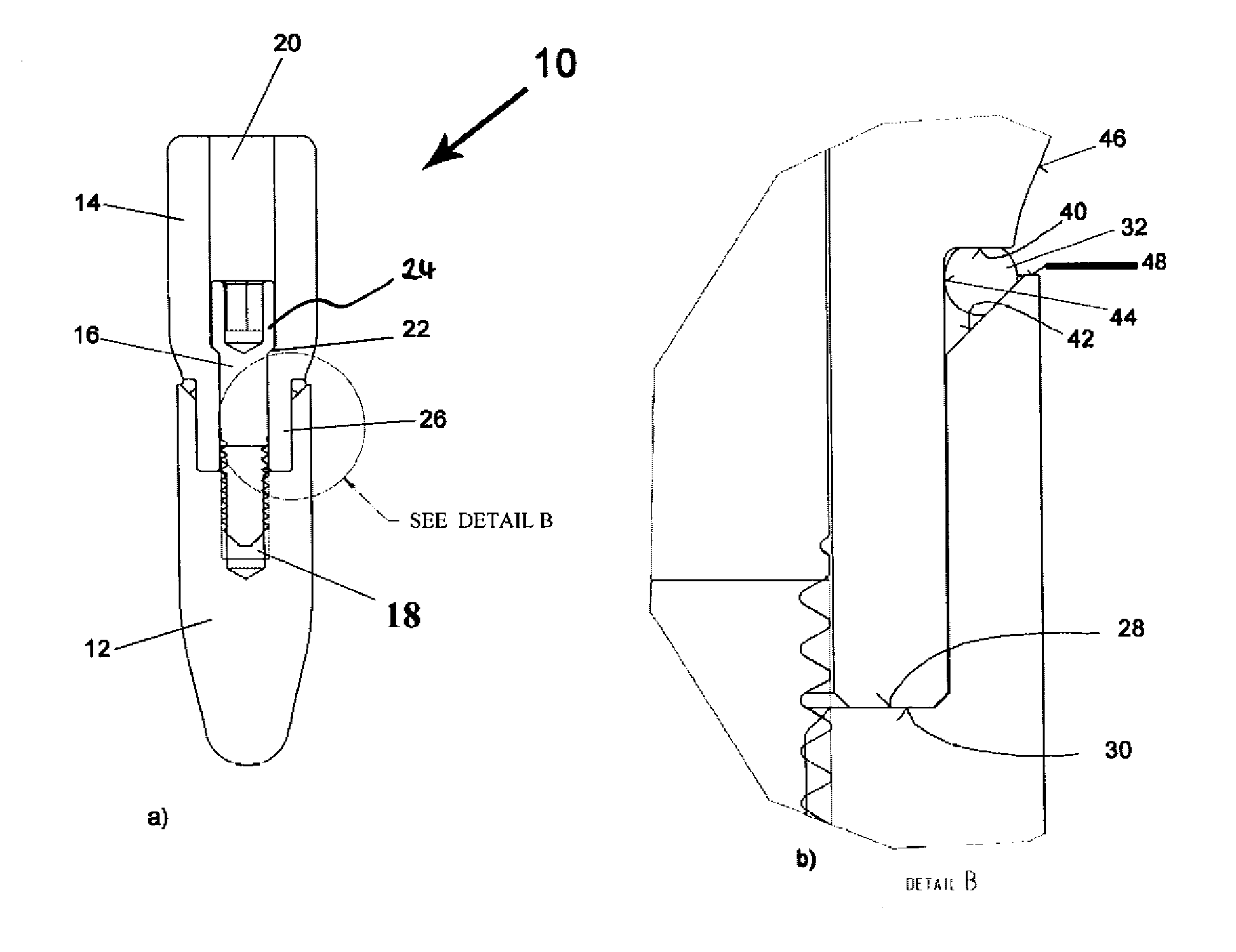
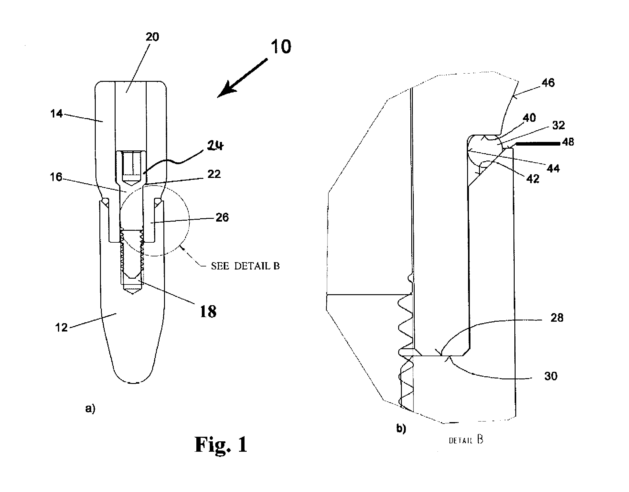
[0064]FIG. 1 shows a first variant of a two-part tooth implant 10. The two-part tooth implant comprises a distant implant part 12, also referred to as distal partial stem, which forms an artificial root of the tooth implant 10 and, therefore, is also referred to a root partial stem.

[0065]Moreover, the tooth implant 10 comprises a proximal implant part 14, which is also referred to as proximal partial stem or build-up partial stem. The proximal implant part 14 serves for accommodating an artificial tooth crown (not shown).

[0066]As can be seen in FIG. 1a, the distal implant part 12 and the proximal implant 14 are connected to one another in the fully assembled state by means of a stud bolt 16. To this end, there is provided in the distal implant part 12 a blind hole 18 with an internal thread. The blind hole 18 runs along a central longitudinal axis of the distal implant part 12.

[0067]In the proximal implant part 14, there is provided a stepped longitudinal bore 20 along a longitudina...


PUM


Abstract

The invention relates to a multi-part tooth implant with at least a proximal implant part and a distal implant part that are to be connected to each other such that a connection site is obtained when the two implant parts are in the connected state. An annular sealing element is arranged at this connection site and, in the fully assembled state of the tooth implant, is clamped between mutually opposite sealing surfaces, namely a sealing surface of the proximal implant part and a sealing surface of the distal implant part, such that the sealing element has an outer surface portion that forms part of the outer contour of the tooth implant. The two sealing surfaces initially approach each other in a direction oriented outwards from a central longitudinal axis of the tooth implant. The sealing surfaces merge into outer surfaces of the tooth implant at the place where, in the outer contour of the fully assembled tooth implant, a surface portion formed by the sealing element in each case adjoins a surface portion formed by the respective implant part. These outer surfaces move away from each other in the outwardly oriented direction.

Description

BACKGROUND[0001]The invention relates to a multi-part tooth implant with at least a proximal implant part and a distal implant part that are to be connected to each other such that a connection site is obtained when the two implant parts are in the connected state. An annular sealing element is provided between the two implant parts.[0002]Tooth implants of this type are known, for example, from DE 20 2005 015 074, DE 299 24 510 or U.S. Pat. No. 4,756,689. In all these cases, a distal implant part serves as an artificial tooth root which can be screwed into a jawbone at the respective site prior to attaching a proximal implant part and, if necessary, further implant parts to the distal implant part. The proximal implant part usually serves as a build-up partial stem and carries an artificial tooth crown. In many cases, the distal and the proximal implant parts are connected to one another by a cylinder screw.[0003]At the connection site between the distal and the proximal implant par...

Claims


Application Information

Patent Timeline
Patent Type & Authority Patents(United States)
IPC IPC(8): A61C8/00
CPCA61C8/0086A61C8/005A61C8/0059
Inventor MEHRHOF, JURGEN
Owner MEHROF IMPLANT TECH GMBH
Why Eureka
Try Eureka