Low-cost offset stacked power connector

a technology of offset stacked and power connectors, which is applied in the direction of electrical apparatus casings/cabinets/drawers, coupling device connections, instruments, etc., can solve the problems of two separate connectors, graphics cards may require so much power, and often limited power on computer system boards, etc., to achieve easy and less costly manufacturing, more power, and small footprint

Active Publication Date: 2016-10-04
NVIDIA CORP
View PDF57 Cites 0 Cited by
  • Summary
  • Abstract
  • Description
  • Claims
  • Application Information

AI Technical Summary

Benefits of technology

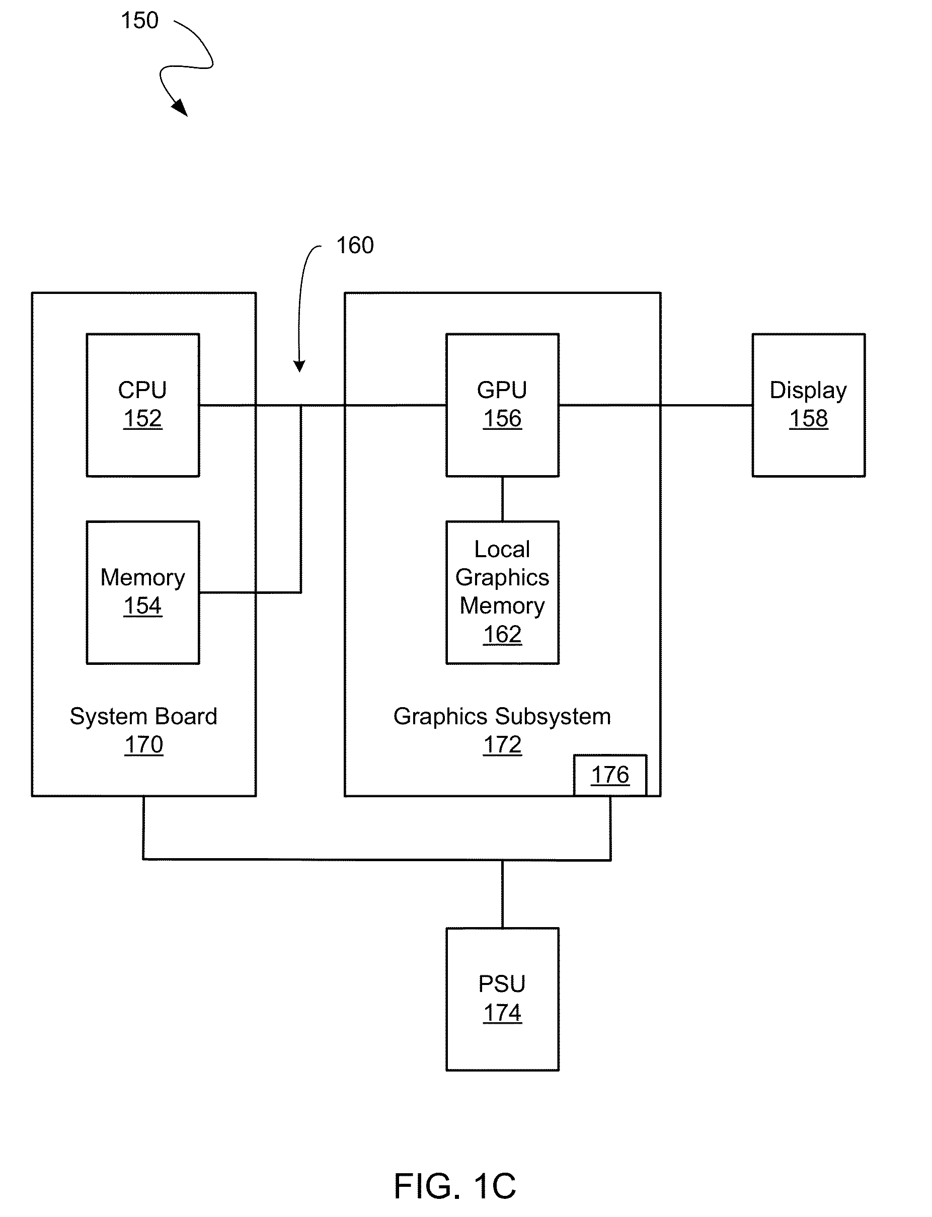
[0007]Accordingly, a need exists for a low-cost connector that may provide more power with a smaller footprint, may be compatible with industry standards without the use of an adapter, and is easier and less costly to manufacture. Additionally, a need exists for a connector, e.g., for a graphics subsystem card, that may be easier for a user to disconnect plugs from and also is easier and less costly to manufacture. Embodiments of the present invention provide novel solutions to these needs and others as described below.

Problems solved by technology

However, as the processing power of video cards has increased, so has their requirements for power.
At the same time, computer system boards are often limited in the amount of power that they may provide.
Some graphics cards may require so much power that two separate connectors are required.
While the demand for graphics cards with a smaller form factor increases, the printed circuit boards included in the graphics cards become more densely populated.
However, including two separate connectors is costly and disconnecting at least one of the connectors may be difficult without the use of a tool when the connectors are positioned across from each other.
In addition, such a side-by-side connector configuration may disadvantageously affect the placement or quality of a cooling fan 106 (see FIG. 1B).
For example, due to inherent factors in graphics card design and other limitations such as specification limitations or OEM requirements, the power connectors may be located either directly under or directly adjacent to the fan 106.
Moreover, as the power consumption of graphics cards has increased, manufacturers have relied on larger fans to cool components of the graphics card.
The fan size may be limited by the size and location of the power connectors.
As a result, the airflow of the fan may be obstructed, causing inefficient air flow and acoustic noise in the environment.
While some specifications may permit the use of an adapter that couples a standard connector to a proprietary connector which attempts to address these issues, such an adapter may be prohibitively costly and less convenient for a user.

Method used


Image

  • Low-cost offset stacked power connector
  • Low-cost offset stacked power connector
  • Low-cost offset stacked power connector

Examples


Embodiment Construction

[0031]Reference will now be made in detail to embodiments of the present invention, examples of which are illustrated in the accompanying drawings. While the present invention will be discussed in conjunction with the following embodiments, it will be understood that they are not intended to limit the present invention to these embodiments alone. On the contrary, the present invention is intended to cover alternatives, modifications, and equivalents which may be included with the spirit and scope of the present invention as defined by the appended claims. Furthermore, in the following detailed description of the present invention, numerous specific details are set forth in order to provide a thorough understanding of the present invention. However, embodiments of the present invention may be practiced without these specific details. In other instances, well-known methods, procedures, components, and circuits have not been described in detail so as not to unnecessarily obscure aspect...


PUM


Abstract

Embodiments of the present invention may be directed to an electronic connector. More specifically, the electronic connector may include a single connector body and a mounting end operable to couple the single connector body with an electronic board of an electronics unit. The electronic connector may also include a lower jack portion disposed in the single connector body and include multiple lower pin receptacles, where the lower jack portion is disposed adjacent to the mounting end and is operable to receive a first connector end of a first cable. The electronic connector may further include an upper jack portion disposed in the single connector body and include multiple upper pin receptacles, where the upper jack portion is disposed above the lower jack portion and is operable to receive a second connector end of a second cable.

Description

BACKGROUND OF THE INVENTION[0001]Graphics cards commonly receive electrical power from a computer system board, for example, through a PCI Express (PCIe) connection. However, as the processing power of video cards has increased, so has their requirements for power. At the same time, computer system boards are often limited in the amount of power that they may provide. For example, the PCIe specification limits the power supply from the computer system board to 75 Watts.[0002]As a result, graphics cards that require more power may receive power from sources other than a computer system board, for example, graphics cards may receive power directly from a power supply unit. Such graphics cards may connect with the power supply unit through a connector that is separate from the connector that connects the graphics card to the computer system board.[0003]Some graphics cards may require so much power that two separate connectors are required. While the demand for graphics cards with a sma...

Claims


Application Information

Patent Timeline
Patent Type & Authority Patents(United States)
IPC IPC(8): H01R12/00H01R27/02H01R12/70G06F1/18H01R13/627
CPCH01R27/02G06F1/185G06F1/189H01R12/7088H01R13/6273
Inventor LOTTER, ERIC MICHAELMCSHERRY, ERIC MICHAELLOILER, BRIAN ROGERCHAPMAN, DAVID ANDREWMORALES, JR., ANTHONY JOSENGUYEN, AN
Owner NVIDIA CORP
Why Eureka
Try Eureka