
Controlling operation of a timing device using an OTP NVM to store timing device configurations in a RAM

Active Publication Date: 2016-09-27
INTEGRATED DEVICE TECH INC
View PDF90 Cites 4 Cited by
  • Summary
  • Abstract
  • Description
  • Claims
  • Application Information

AI Technical Summary

Benefits of technology

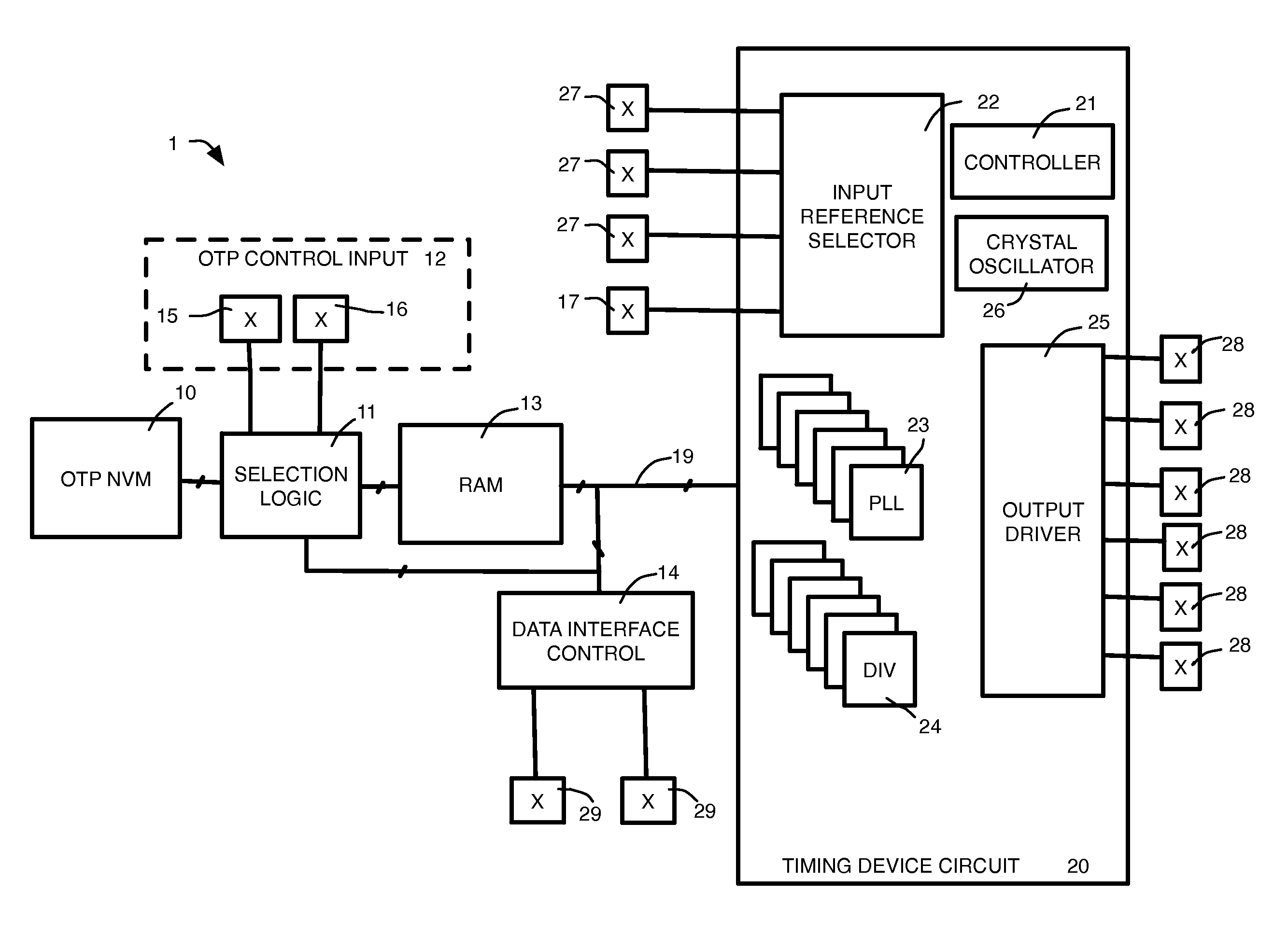
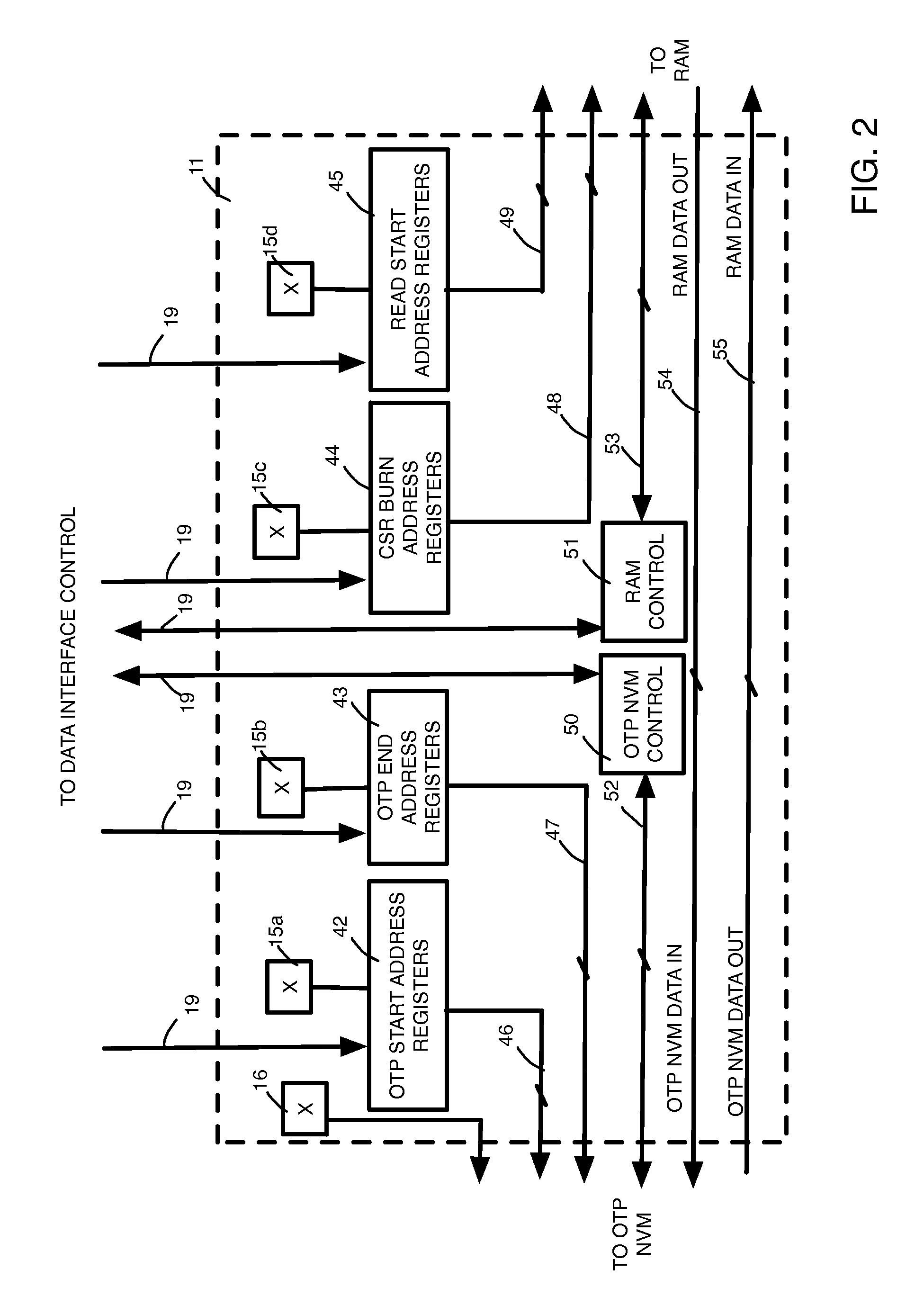
The present invention provides methods and devices that allow for flexibility in the way configuration data is loaded into RAM. Unlike previous devices, the present invention does not require the OTP NVM addresses to match the RAM addresses. This provides users with more flexibility in timing device configurations.

Problems solved by technology

However, conventional data structures in the OTP and in the RAM limit the flexibility of the system.

Method used


Image

  • Controlling operation of a timing device using an OTP NVM to store timing device configurations in a RAM
  • Controlling operation of a timing device using an OTP NVM to store timing device configurations in a RAM
  • Controlling operation of a timing device using an OTP NVM to store timing device configurations in a RAM

Examples


Embodiment Construction

[0016]Reference will now be made in detail to the preferred embodiments of the invention, examples of which are illustrated in the accompanying drawings. While the invention will be described in conjunction with the preferred embodiments, it will be understood that they are not intended to limit the invention to these embodiments. On the contrary, the invention is intended to cover alternatives, modifications and equivalents, which may be included within the spirit and scope of the invention as defined by the appended claims. Furthermore, in the following detailed description of the present invention, numerous specific details are set forth in order to provide a thorough understanding of the present invention. However, it will be obvious to one of ordinary skill in the art that the present invention may be practiced without these specific details. In other instances, well-known methods, procedures, components, and circuits have not been described in detail so as not to unnecessarily...


PUM


Abstract

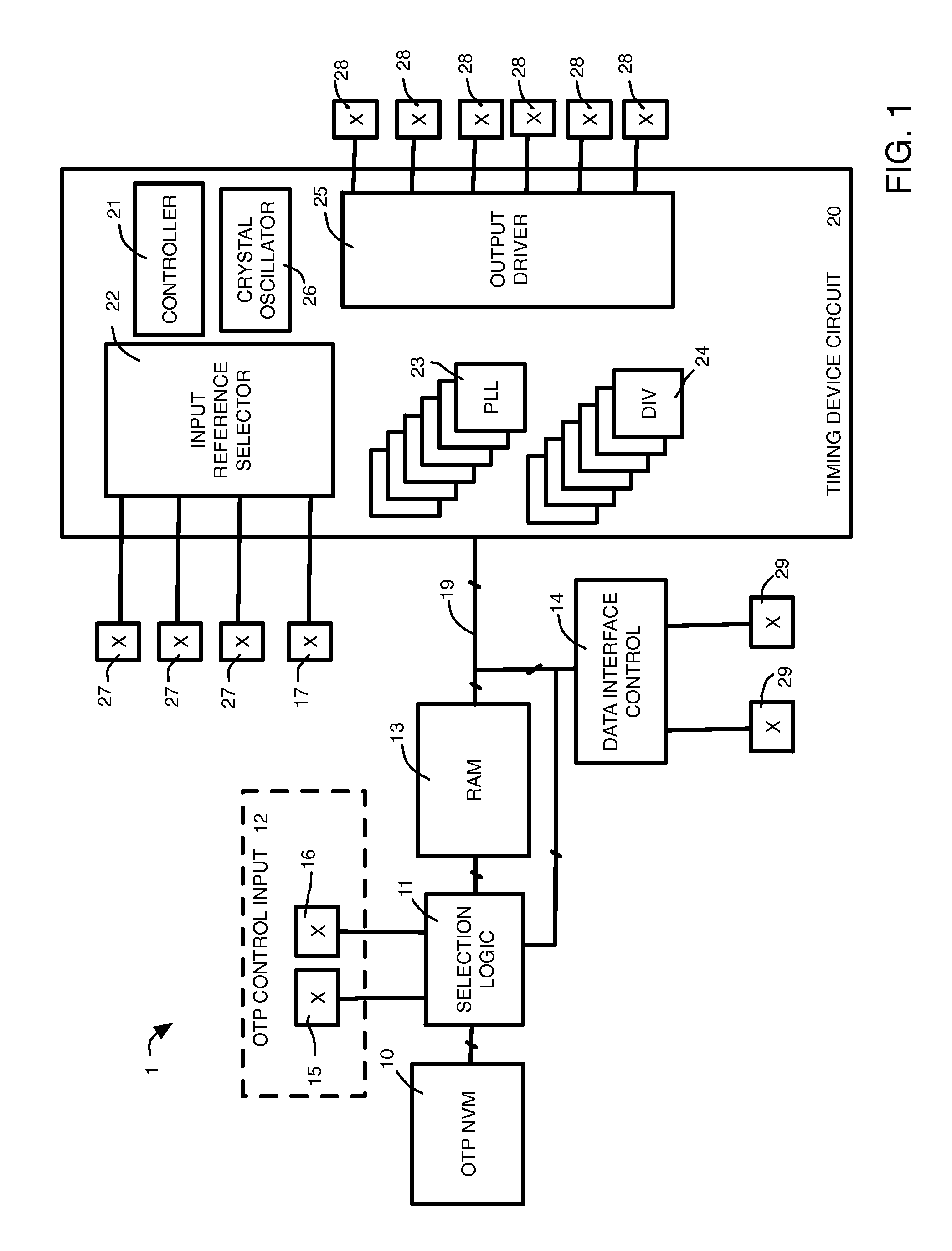
The present invention provides a method and apparatus that includes a timing device circuit for generating a timing signal, a RAM coupled to the timing device circuit, an OTP NVM and selection logic. The RAM is operable upon receiving a burn address to read configuration data in the RAM beginning at the burn address and the OTP NVM is operable to burn the configuration data read from RAM into the OTP NVM. The OTP NVM is configured to read configuration data in the OTP NVM and the RAM is configured to store the configuration data from the OTP NVM beginning at an address in the RAM corresponding to a read start address to define a timing device configuration in the RAM.

Description

BACKGROUND OF THE INVENTION[0001]Programmable timing devices must have a basic set of configuration parameters at each power-on of the timing device in order to generate the required timing device output. Typically, at a power-on of a programmable timing device, typically referred to as a “power-on reset,” the timing device receives a configuration at data interface control circuits of the timing device such as an Inter-IC (I2C) interface or a system management bus (SMB) interface. This configuration is loaded into the timing device and is used to control the initial operation of the timing device.[0002]In order to eliminate the need for receiving configuration data at each power-on reset, timing device have been developed that are configured to be connected to external read only memory (ROM) that includes the required timing device configuration. At power-on reset the timing device configuration from the external ROM is loaded into the timing device to control the initial operation...

Claims


Application Information

Patent Timeline
IPC IPC(8): G11C17/00G11C17/18G11C17/16
CPCG11C17/18G11C17/16G06F1/24G11C7/20G11C7/222
Inventor ZHENG, XIAOHONGLI, HUI
Owner INTEGRATED DEVICE TECH INC
Learn More