
Luminous multiple glazing unit comprising light-emitting diodes

a technology of light-emitting diodes and insulating glazing units, which is applied in the direction of lighting elements, lighting and heating apparatus, instruments, etc., can solve the problems that the optical performance of the light-emitting diode-comprising insulating glazing units is not optimized, and achieves the effect of easy and quick production

Active Publication Date: 2016-09-27
SAINT-GOBAIN GLASS FRANCE
View PDF14 Cites 7 Cited by
  • Summary
  • Abstract
  • Description
  • Claims
  • Application Information

AI Technical Summary

Benefits of technology

The aim of this patent is to create a simple and efficient multiple glazing unit that is easy and quick to produce, reliable, and meets industry requirements. The invention is designed to be a luminous insulating glazing unit that can be used in various settings, such as in buildings or vehicles.

Problems solved by technology

The Applicant has observed that this light-emitting-diode-comprising insulating glazing unit is not optimized in terms of optical performance.

Method used


Image

  • Luminous multiple glazing unit comprising light-emitting diodes
  • Luminous multiple glazing unit comprising light-emitting diodes
  • Luminous multiple glazing unit comprising light-emitting diodes

Examples


first embodiment

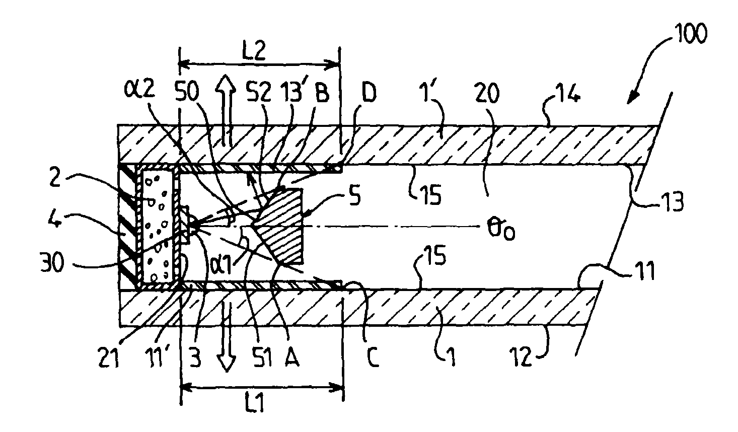
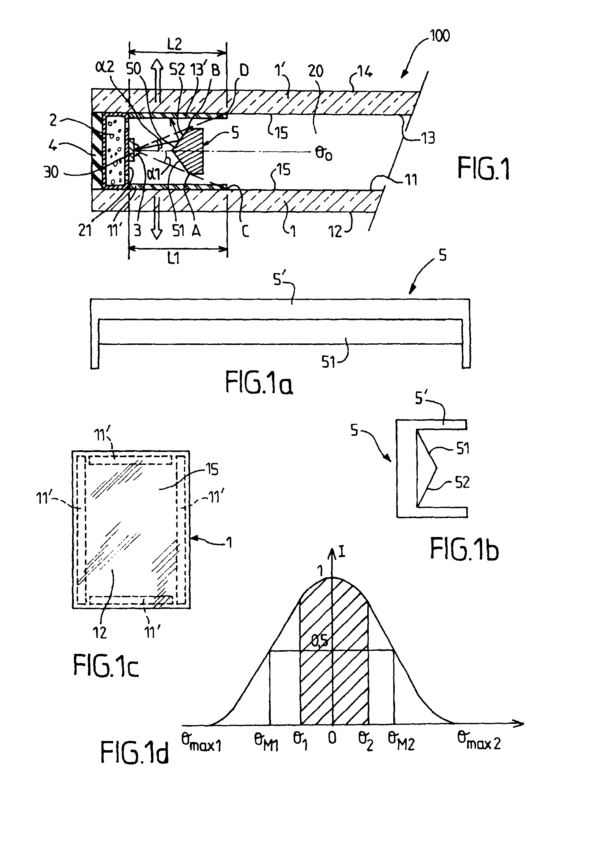
[0164]FIG. 1 shows a schematic view of a partial longitudinal cross section through a multiple glazing unit 100 comprising light-emitting diodes in the invention.

[0165]The glazing unit 100, here an insulating glazing unit, comprises:[0166]a first flat glass element 1 made of mineral glass, with first and second main faces 11, 12, for example a square (or rectangular, etc.) glass sheet;[0167]a second flat glass element 1′, with the main face, called the third face 13, lying opposite the first face, and another main face 14, called the fourth face, for example a square (or rectangular, etc.) glass sheet;[0168]the first and second elements being securely fastened to and spaced apart from each other;[0169]an internal space, between the first and third faces, this space especially being evacuated or filled with a gas, such as one or more inert gases or air;[0170]a spacer 2 separating the first and second glass elements at the periphery of the glazing unit, bounding the internal gas-fille...

second embodiment

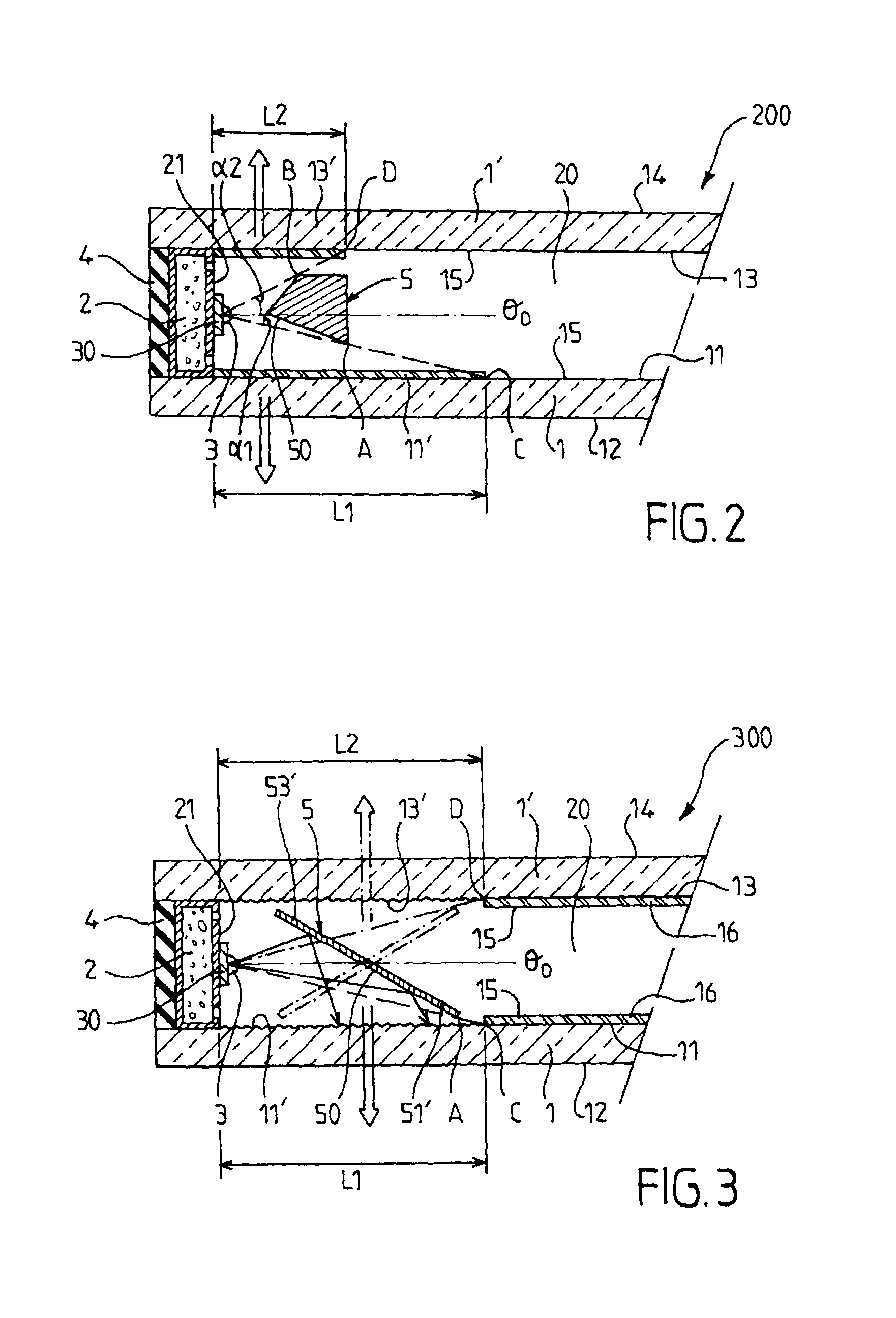
[0220]FIG. 2 shows a schematic view of a partial longitudinal cross section through a luminous multiple glazing unit 200 comprising light-emitting diodes in the invention.

[0221]The glazing unit 200 differs from the glazing unit 100 in that the obliquity of the second central area is larger causing the width L2 to be smaller than L1.

third embodiment

[0222]FIG. 3 shows a schematic view of a partial longitudinal cross section through a luminous multiple glazing unit 300 comprising light-emitting diodes (LEDs) in the invention.

[0223]The glazing unit 300 differs from the glazing unit 100 in that the reflector used 5, 50 here can move, meaning that:[0224]in a first position, all of the first luminous zone 11′ (and optionally a fraction of the second luminous zone 12′) is illuminated; and[0225]in a second position, all of the second luminous zone 13′ (and optionally a fraction of the first luminous zone) is illuminated.

[0226]In the first position (solid lines) a first reflective area, called the central are 50, of the reflector makes an oblique angle to the first face, this central area being able to reflect, with one or more lateral reflective areas 53′ and 51′ if required, what are called central rays emitted by said first group of diodes, the central rays including rays emitted along the main emission direction or main emission di...


PUM


Abstract

A luminous multiple glazing unit including: first and second flat glass elements; light-emitting diodes located in an internal space; a reflector including a part fixed to the glazing unit in the internal space; and a first luminous zone associated with the first glass element. In a first configuration, the reflector has a central reflective area for reflecting at least 30% of total flux emitted by the diodes in the group onto a first mechanism scattering light, or, in a second configuration, the reflector forms a beam splitter and has a double-image central reflective area of a first central area for reflecting first central rays onto a first mechanism scattering light and a second central area for reflecting second central rays onto a second scattering mechanism, the reflector reflecting at least 30% of total flux emitted by the diodes in the group.

Description

BACKGROUND[0001]The present invention relates to a luminous multiple glazing unit and more particular to a luminous multiple glazing unit comprising light-emitting diodes.[0002]Light-emitting diodes or LEDs were originally employed as status or indicator lights in electrical and electronic appliances but have already, for a number of years, been used as light sources in signaling devices such as traffic lights, in automotive vehicle lighting (indicators, side lights) or in torches or path lighting. Light-emitting diodes are advantageous because of their long lifetime, their luminous efficiency, their robustness and their compactness, making systems using them more durable and easier to maintain.[0003]Document DE 10 322 561 describes an insulating double glazing unit, for illuminating the façades of buildings, comprising (in the embodiment corresponding to FIG. 4 in this document DE 10 322 561):[0004]a first glazing pane with internal and external faces;[0005]a second glazing pane wi...

Claims


Application Information

Patent Timeline
Patent Type & Authority Patents(United States)
IPC IPC(8): F21V1/00E06B3/66F21V8/00
CPCE06B3/66G02B6/0096F21V7/00F21V33/00E05Y2800/106
Inventor MONTGERMONT, AUDEZHANG, JINGWEIDELHORME, DAVID
Owner SAINT-GOBAIN GLASS FRANCE
Learn More