Electric storage battery support apparatus

a technology for supporting apparatus and electric storage batteries, which is applied in the direction of electrical apparatus, cell components, cell component details, etc., can solve the problems of increasing aerodynamic drag on the vehicle, and achieve the effects of minimizing the cost of the piece, minimizing the mass and the number of fasteners, and minimizing the aerodynamic drag

Active Publication Date: 2016-09-06
GM GLOBAL TECH OPERATIONS LLC
View PDF10 Cites 2 Cited by
  • Summary
  • Abstract
  • Description
  • Claims
  • Application Information

AI Technical Summary

Benefits of technology

[0005]The tray insulates the batteries against harm due to the ambient air temperature in the operating environment.
[0006]The tray is formed as a one-piece casting that minimizes aerodynamic drag without need for a cover over the underside of the tray.
[0007]The one piece design minimizes mass and the number of fasteners. Because tooling normally used to accommodate a multi-piece design is not required during vehicle assembly and component assembly, the tray design minimizes piece cost and requires low investment cost and reduces tooling lead time.
[0008]The ribs enable the structural, crash, and durability requirements of the tray to be realized.

Problems solved by technology

Such battery tray panels, however, have a large number of indentations and holes for fasteners, which increase aerodynamic drag on the vehicle.

Method used


Image

  • Electric storage battery support apparatus
  • Electric storage battery support apparatus
  • Electric storage battery support apparatus

Examples


Embodiment Construction

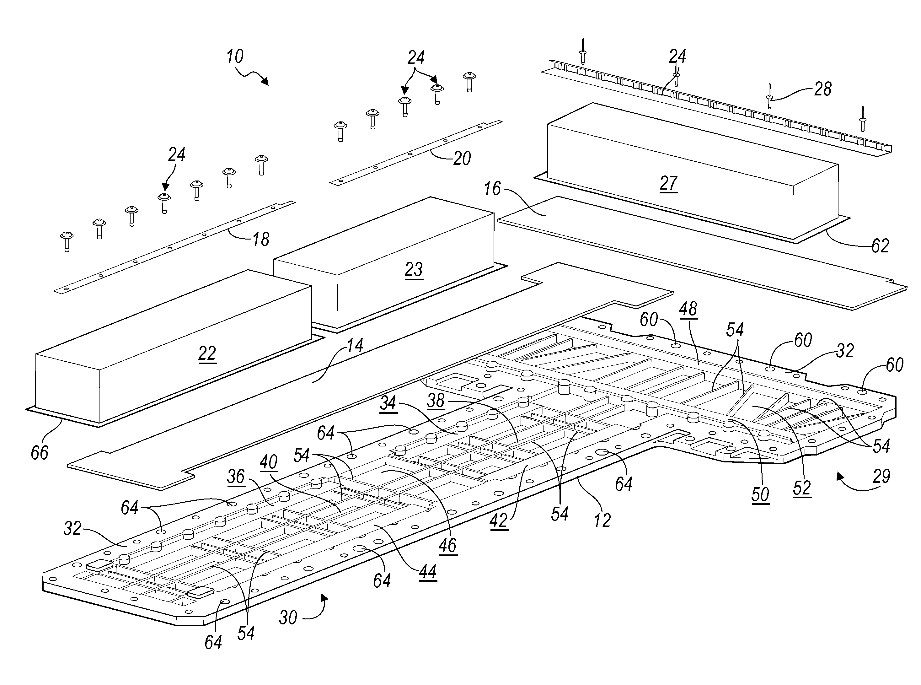
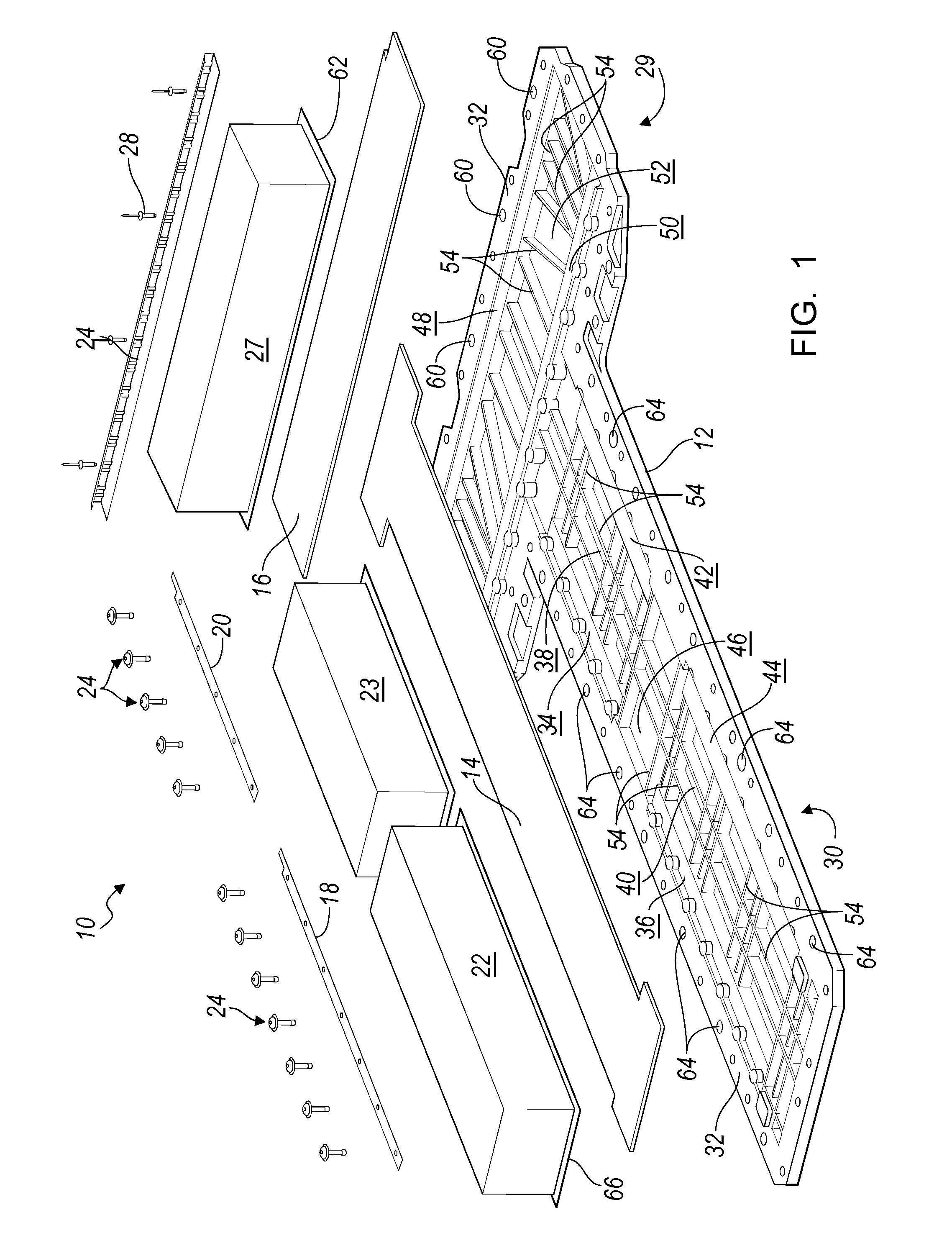
[0013]Referring now to the drawings, there is illustrated in FIG. 1 a battery support assembly 10, which includes a tray 12; sheets of thermal insulation 14, 16; fastening strips 18, 20 for securing a lateral edge of batteries 22, 23 to the tray; screws 24 for securing the fastening strips to the tray; a channel 26 for securing battery 27 to the tray; and rivets 28 for securing the channel 26 to the tray.

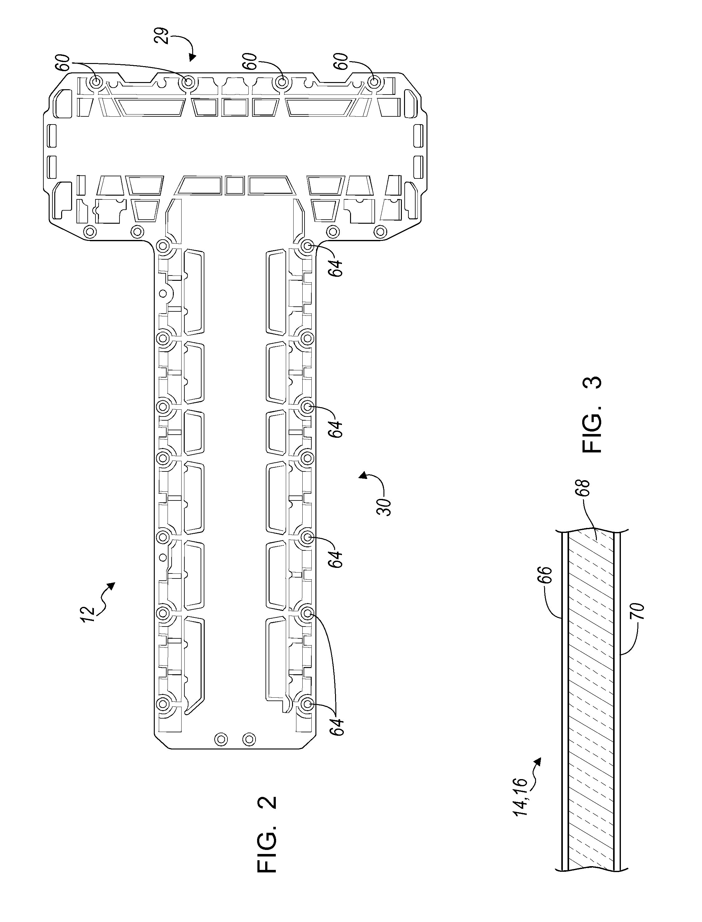
[0014]Tray 12 is preferably a casting of magnesium alloy, which when viewed from above is tee-shaped having a cross leg 29 and a stem 30. The upper surface of the tray 12 comprises multiple planar support surfaces and a flat plane 32, which extends around an outer periphery of the tray 12 and is located outboard of the support surfaces.

[0015]Two of the support surfaces 34, 36 extend adjacent to plane 32 along the left-hand side of rectangular recesses 38, 40 formed in the stem 30.

[0016]Two of the support surfaces 42, 44, adjacent to plane 32, extend along the right-hand side of the ...


PUM

PropertyMeasurementUnit
depthaaaaaaaaaa
thicknessaaaaaaaaaa
lengthaaaaaaaaaa

Abstract

An apparatus for supporting a battery comprises a tray including a support surface, a recess having a elevation that is lower than an elevation of the support surface, ribs located in the recess and extending to the elevation of the support surface, thermal insulation supported on the ribs and the upper surface, and a battery contacting the insulation and supported on the ribs and the support surface.

Description

BACKGROUND OF INVENTION[0001]The present invention relates generally to an apparatus for supporting and insulating an electric storage battery in an electric vehicle.[0002]A rechargeable electric storage battery is mounted on a tray and located at the underside of a vehicle with its lower surface exposed to the road. It has been conventional practice to form such battery trays in multiple pieces of high strength material, with such multiple stampings welded together. The lower surface of the tray is covered with a panel. Such battery tray panels, however, have a large number of indentations and holes for fasteners, which increase aerodynamic drag on the vehicle.[0003]A battery tray casting in one-piece would reduce overall complexity of a battery tray formed of multiple welded stampings. Preferably the lower surface of a one-piece tray would reduce aerodynamic drag and avoid the need for a panel covering bolted to the bottom of the battery tray.SUMMARY OF INVENTION[0004]An apparatus...

Claims


Application Information

Patent Timeline
Patent Type & Authority Patents(United States)
IPC IPC(8): H01M2/10H01M10/625H01M10/613H01M10/658H01M50/209
CPCH01M2/1077H01M2/1072H01M2/1083H01M10/613H01M10/625H01M10/658Y02E60/10H01M50/209
Inventor QUINN, SHAWN G.FADLER, GREGORY J.SCHACHERMEYER, BRIAN J.DECLERCK, DAVID B.GANDHI, MILIND S
Owner GM GLOBAL TECH OPERATIONS LLC
Why Eureka
Try Eureka