Deflector device and motor vehicle in which the front shield carries said deflector device

a deflector and front shield technology, applied in the field of motor vehicles, can solve the problems of consuming a lot of fuel of vehicles, and achieve the effects of reducing the drag of vehicles, high deflector efficiency, and real-time deflector efficiency

Active Publication Date: 2015-10-08
CO PLASTIC OMNIUM
View PDF1 Cites 2 Cited by
  • Summary
  • Abstract
  • Description
  • Claims
  • Application Information

AI Technical Summary

Benefits of technology

[0013]Thus the deflector covers not only the bottom line at the front, in an essentially straight area but covers the entire bottom line at the front, highly curved, including the two returns to the wheels. This provides a barrier which projects well forward, up to the wheels, to drive the air towards the sides. It is this combination of a barrier at the front, along the entire length, which makes the deflector truly efficient.
[0029]Thus, this additional deflector minimizes the aerodynamic drag caused by the wheel.

Problems solved by technology

These vehicles, in fact, consume a lot of fuel due to the high drag caused by the ground clearance

Method used


Image

  • Deflector device and motor vehicle in which the front shield carries said deflector device
  • Deflector device and motor vehicle in which the front shield carries said deflector device
  • Deflector device and motor vehicle in which the front shield carries said deflector device

Examples


Embodiment Construction

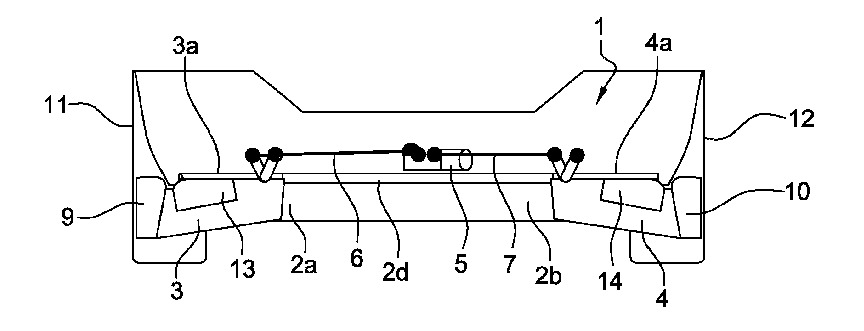
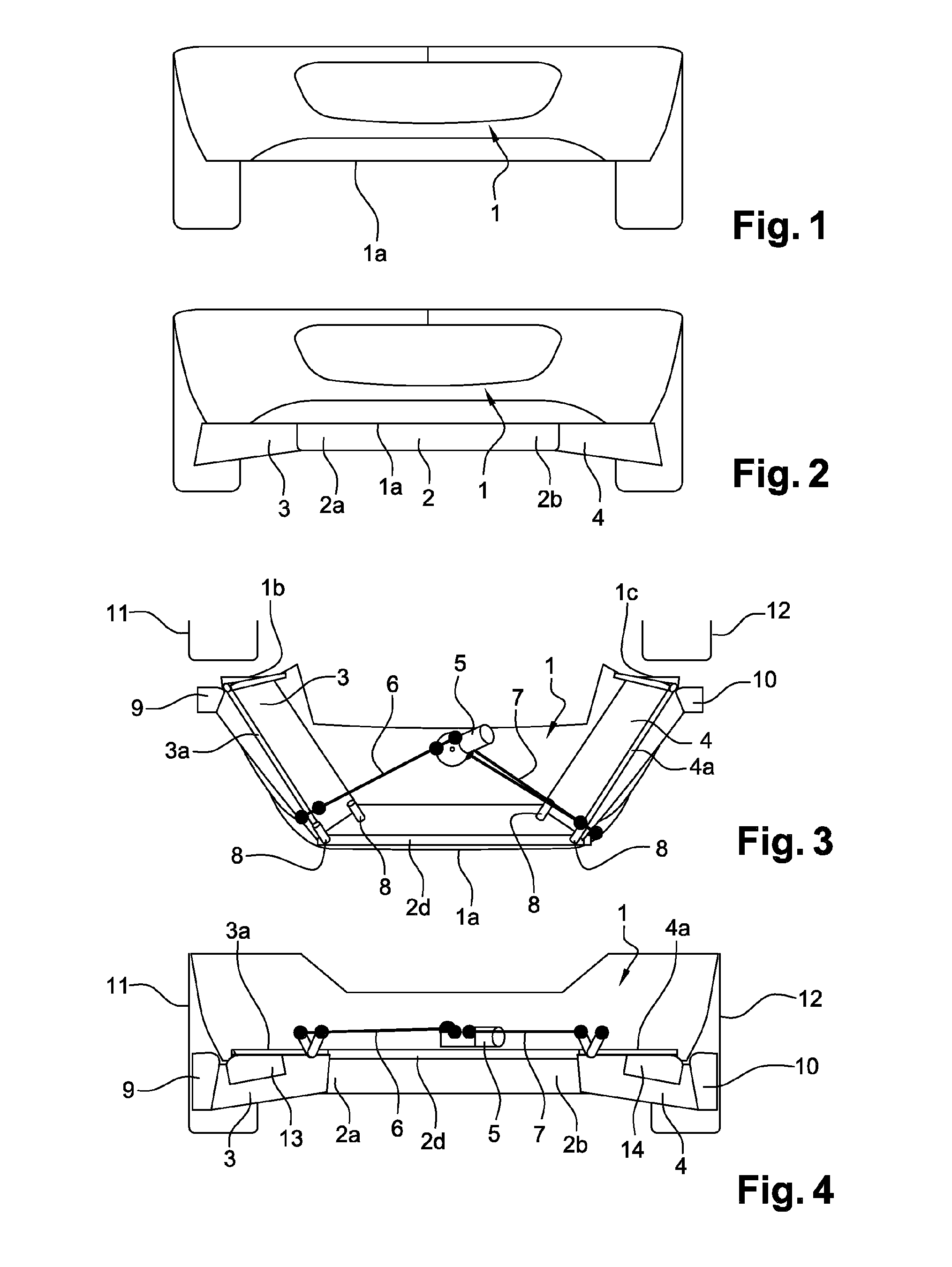
[0040]FIGS. 1 and 2 show a motor vehicle whose front shield 1 comprises deflectors 2, 3, 4 mounted so as to be able to pivot between a position in which they are folded under the front shield 1 and a position (see FIG. 2) in which these deflectors 2, 3, 4 project downwards.

[0041]According to the invention, the front shield 1 carries a central deflector 2 and two lateral deflectors 3, 4, the central deflector 2 extending, as shown on FIG. 3, near the front bottom edge 1a of the front shield 1 and each of the two lateral deflectors 3, 4 extending between a lateral end 2a, 2b of the central deflector 2 and a lower rear bottom edge 1b, 1 c of the shield 1.

[0042]FIG. 2 also shows a preferred variant of the invention according to which the height of the lateral deflectors 3, 4 is equal to the height of the central shield at the ends of the lateral deflectors 3, 4 near the central deflector 2, the height increasing on moving away from the central deflector 2, so that these lateral deflecto...


PUM


Abstract

A mobile deflector device of a curved vehicle shield, comprising a central deflector and two lateral deflectors, essentially forming three chords distributed over the entire length of the shield. Each of the three deflectors is mounted such as to be able to pivot between a folded position and a second unfolded position substantially perpendicular to the first position.

Description

CROSS-REFERENCE TO RELATED APPLICATIONS[0001]This application claims priority to PCT Application No. PCT / EP2013 / 066088 filed Jul. 31, 2013, which claims priority to the French application 1257751 filed on Aug. 10, 2012, which applications are incorporated herein by reference and made a part hereof.BACKGROUND OF THE INVENTION[0002]1. Field of the Invention[0003]This invention relates to a motor vehicle whose front shield comprises several deflectors mounted such as to be able to pivot between a folded position under the front shield and a position in which the deflectors project downwards.[0004]2. Description of the Related Art[0005]Vehicles comprising such deflectors are described, for example, in French Patents Nos. 2 821 593, 2 927 303 and 2 864 811.[0006]Such deflectors are designed to reduce the drag of the vehicle and its consumption especially at high speed.[0007]When the deflectors are in the folded position under the front shield, they are protected from impacts against obst...

Claims


Application Information

Patent Timeline
Patent Type & Authority Applications(United States)
IPC IPC(8): B62D35/02B62D35/00
CPCB62D35/005B62D35/02Y02T10/82
Inventor GUINOIS, PASCALDROUOT, LAURENTGILOTTE, PHILIPPE
Owner CO PLASTIC OMNIUM
Why Eureka
Try Eureka