
Coordinate input apparatus, method thereof, and storage medium

a technology of input apparatus and input data, applied in the field of coordinate input apparatus, can solve the problems of generating quantization error, slight error in either method, and generating several errors owing to its structure, and achieve the effect of improving the discontinuity of coordinates

Active Publication Date: 2016-09-06
CANON KK
View PDF25 Cites 0 Cited by
  • Summary
  • Abstract
  • Description
  • Claims
  • Application Information

AI Technical Summary

Benefits of technology

[0012]The present invention improves the discontinuity of coordinates at the boundary between regions when an effective coordinate input region is divided into a plurality of regions and the coordinates of a pointed position are calculated.

Problems solved by technology

In such an apparatus, several errors are generated owing to its structure.
Since each pixel receives light in the light receiving device, a quantization error is generated at this time.
However, a slight error is generated in either method.
At this time, a measurement error or the like is generated.
If the attaching position of the apparatus shifts owing to aged deterioration or the like, an error may be further generated.
Owing to various error factors as mentioned above, an angle detected by the sensor has an error.
In this system, if an error is generated in an angle detected by the sensor unit, another problem that coordinate values do not coincide with each other at the boundaries between the plurality of divided regions is generated, in addition to the problem that a touched position and calculated coordinates on the screen do not match each other.
The other problem arises from the difference in the appearance of an error (direction and distance of an error) between the plurality of divided regions.
Such an error is very noticeable.

Method used


Image

  • Coordinate input apparatus, method thereof, and storage medium
  • Coordinate input apparatus, method thereof, and storage medium
  • Coordinate input apparatus, method thereof, and storage medium

Examples


first embodiment

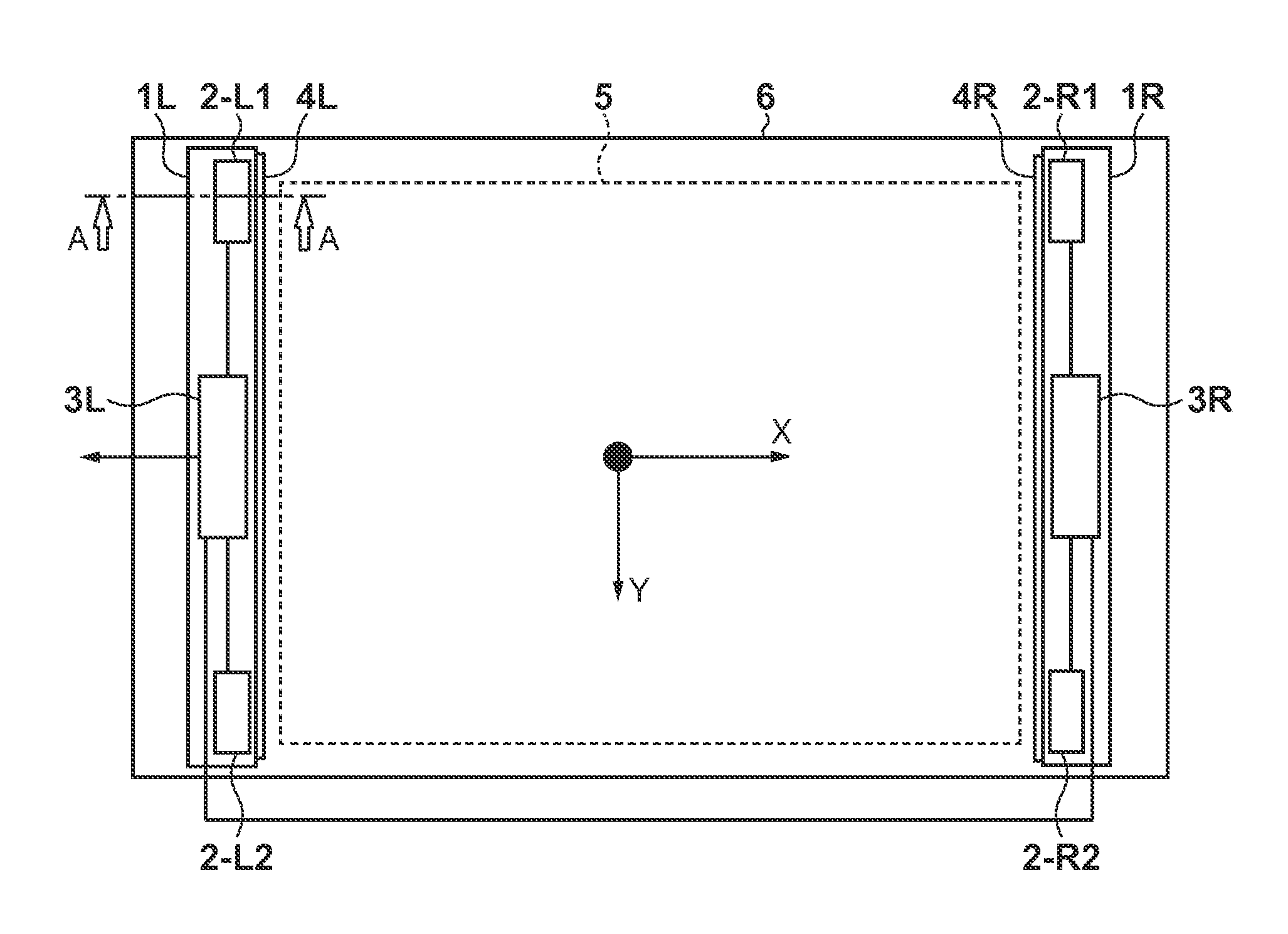
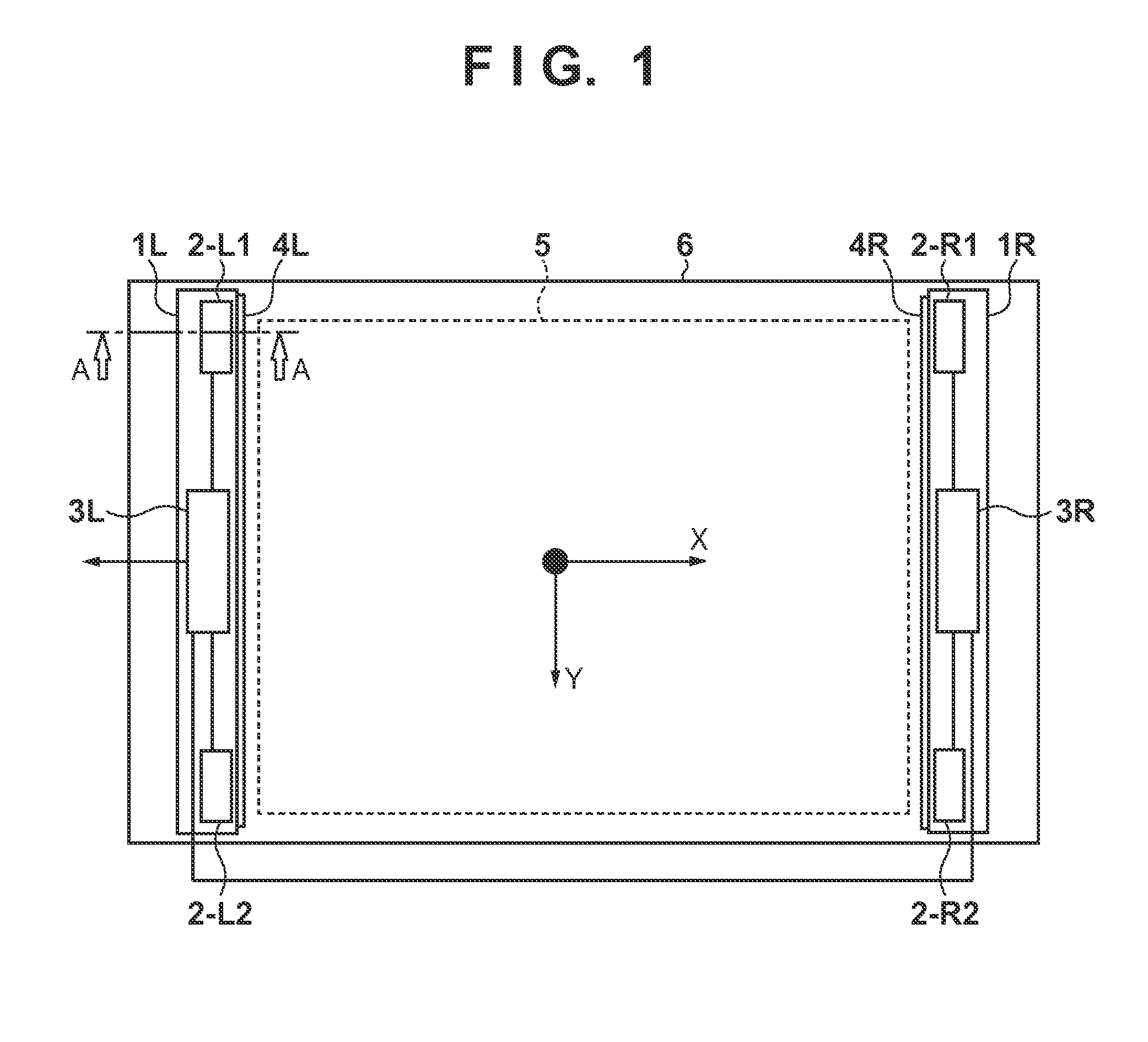
[0030]The schematic arrangement of a coordinate input apparatus will be explained with reference to FIG. 1.

[0031]In FIG. 1, a sensor bar 1L is a housing equipped with at least two sensor units 2-L1 and 2-L2 (first and second sensor units) serving as angle detection sensor units. A sensor bar 1R is a housing equipped with sensor units 2-R1 and 2-R2 (third and fourth sensor units).

[0032]As shown in FIG. 1, the sensor bars 1L and 1R (to be generically referred to as sensor bars 1) are arranged outside two facing sides of a rectangular effective coordinate input region 5. The sensor bars 1L and 1R are parallel and have the same length.

[0033]If a display apparatus is a front projector, the display region is set within the range of the effective coordinate input region 5 and projected onto a flat whiteboard 6, a wall surface, or the like.

[0034]As shown in FIG. 1, retroreflecting members 4L and 4R (to be generically referred to as retroreflecting members 4) are attached to the side surfac...

fourth embodiment

[0171]An example in which eight sensor units are used to cope with a horizontally long screen will be described as the As shown in FIG. 13, a sensor bar 1T is set at the top of an effective coordinate input region 5, and a sensor bar 1B is set at the bottom of the effective coordinate input region 5. The sensor bars 1T and 1B incorporate four sensor units 2-T1 to 2-T4 and four sensor units 2-B1 to 2-B4, respectively. In this form, the sensor bars shown in FIG. 1 are arranged not on the left and right sides of the effective coordinate input region 5 but the top and bottom of the effective coordinate input region 5, and these two sensor bars are combined.

[0172]As shown in FIG. 13, a coordinate system is set by using the sensor unit 2-T1 as an origin. Coordinate calculation of the left half region of the effective coordinate input region 5 is performed by using the four sensor units 2-T1, 2-T2, 2-B1, and 2-B2. Similarly, coordinate calculation of the right half region of the effective...


PUM


Abstract

A coordinate input apparatus which detects a position pointed in a region surrounded by at least four sensor units, based on detection outputs from two sensor units corresponding to the pointed position out of the at least four sensor units stores, in a memory unit, correction values which are based on respective detection outputs of a plurality of combinations each of two sensor units out of the at least four sensor units for one position corresponding to the plurality of combinations, and calculates the pointed position based on the detection outputs from two sensor units corresponding to the pointed position, and the correction values stored in the memory unit.

Description

BACKGROUND OF THE INVENTION[0001]1. Field of the Invention[0002]The present invention relates to a coordinate input apparatus which detects a coordinate position input to a coordinate input surface by a pointer such as a finger in order to input or select information, and a method thereof.[0003]2. Description of the Related Art[0004]Various types of coordinate input apparatuses (touch panels and digitizers) have conventionally been proposed or commercialized. For example, a touch panel is used, which makes it possible to easily operate a terminal such as a PC (Personal Computer) by touching the screen with a finger without using a special tool or the like.[0005]There are various coordinate input methods ranging from a method using a resistive film to a method using an ultrasonic wave. As a method using light, a method (light shielding method) is known, in which a retroreflecting member is arranged outside a coordinate input surface and reflects light from a light projecting unit, an...

Claims


Application Information

Patent Timeline
Patent Type & Authority Patents(United States)
IPC IPC(8): G06F3/041G06F3/042
CPCG06F3/0428
Inventor MATSUSHITA, AKIHIRO
Owner CANON KK
Learn More