Wave energy conversion device

a technology of wave energy and conversion device, which is applied in the direction of machine/engine, engine components, and sea energy generation, can solve the problems of inability to capture more than 50% of wave energy, movement of hydraulic actuators, and inefficiencies, and achieve the effect of improving efficiency and durability of the pump as a power take-off system, reducing frictional losses, and providing corrosion and erosion resistan

Active Publication Date: 2016-08-30
SEAPOWER
View PDF43 Cites 3 Cited by
  • Summary
  • Abstract
  • Description
  • Claims
  • Application Information

AI Technical Summary

Benefits of technology

The invention is about a device that uses two pontoons to capture the energy from waves. One pontoon moves in a different mode than the other, which makes it easier to convert the relative motion of these two pontoons into energy. This results in a more efficient energy conversion than devices that only convert energy from a single mode of motion. The use of seawater as a pump fluid also eliminates the risks associated with hydraulic fluid leakage in a marine environment. Overall, this invention provides a more robust and design-oriented solution for capturing wave energy.

Problems solved by technology

Harnessing wave energy—in particular—presents a number of design challenges with respect to both the efficiency and robustness of systems fit for such a purpose.
However, it is proven that such designs are not capable of capturing more than 50% of the wave energy.
The pontoons heave up and down as waves pass and this causes them to pivot about the centre of the device, causing movement of the hydraulic actuator.
While some of these and other proposals have been commercialised, all such WEC devices rely on a single mode of motion to convert energy from the waves and therefore suffer from the inefficiencies outlined above.
However, it will be appreciated that there are significant environmental risks associated with using oil hydraulics, particularly at sea, where inevitable leaks cause problems.
However, seawater has significant potential to degrade and break down materials exposed to it (through both mechanical and chemical action), and so seawater hydraulic systems need to be able to withstand such forces.
These pumps, however, have very low efficiency (approx 40%) and more importantly, cannot deliver high pressure heads unless multiple pumps are configured in series.
The complexity of such arrangements make them clearly unattractive for implementation in a wave energy converter.
However, these pumps cannot handle raw seawater, as this would lead to rapid wear and component failure, and are therefore limited in their utility.
A disadvantage with such a pump is that the pressure that the flexible hoses can withstand will limit the pressure generated.
In an environment where a high pressure output is desirable (such as in the context of a wave energy converter), this would be a serious limitation.
It will be appreciated that expending energy re-accelerating the fluid body at the start of each second stroke results in energy loss and a significant deterioration in pumping performance.
This may be disadvantageous if continual flow and pressure is desired.
Furthermore, the piston / dual chamber arrangement comprises a single integrated unit that would be difficult to repair, because the surface cooperating with the plunger seal is situated on the inside of the chamber.
Furthermore, leakage in the piston seal would affect the fluid being pumped out of both chambers.
As mentioned above, piston based pumps are of little utility for pumping seawater, because the piston needs high pressure, high velocity, high wear resistance piston seals or rings, and there is nothing on the market yet to achieve this economically.

Method used


Image

  • Wave energy conversion device
  • Wave energy conversion device
  • Wave energy conversion device

Examples


Embodiment Construction

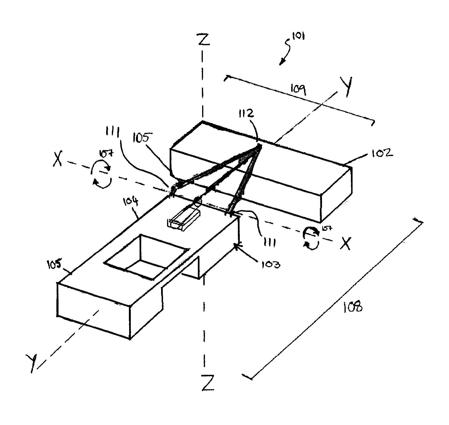
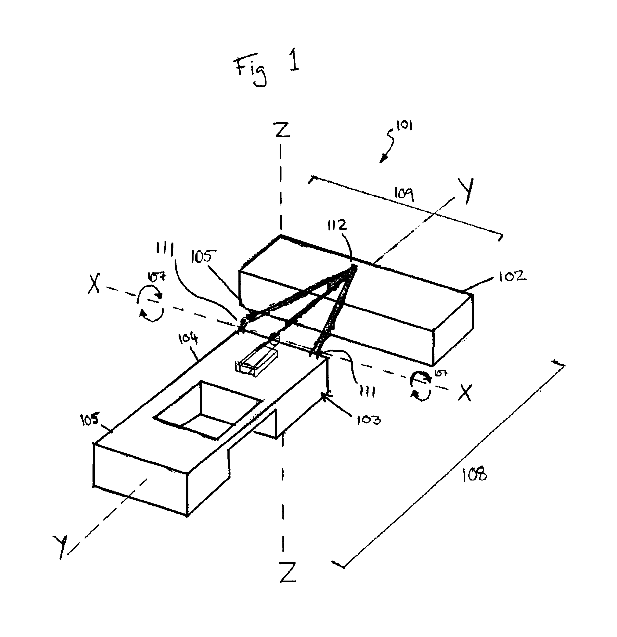
[0087]FIG. 1 illustrates a preferred embodiment of the Wave Energy Converter of the present invention suitable for offshore deployment. Wave Energy Converter 101 (hereafter referred to as WEC), is comprised of at least one forward pontoon 102, and a rear pontoon 103. In some embodiments, the rear pontoon 103 may comprise a central pontoon 104 immovably fixed to at least one outrigger pontoon 106. Forward pontoon 102, is pivotably attached to the rear pontoon 103 by way of drive arm 105. Drive arm 105 is attached to rear pontoon at points 111, and to forward pontoon at point 112. Drive arm 105 forms part of a power take-off (PTO) system as will be described in more detail below.

[0088]Forward pontoon 102 is preferably long and slender in dimension, such that its elongate axis may be aligned—when in use—parallel to the crest of oncoming waves (consistent in orientation with the X axis of FIG. 1), and perpendicular to the waves' direction of propagation (consistent in direction with the...


PUM


Abstract

A wave energy conversion device including a first pontoon configured to respond to an incident wave by operating in at least a first mode of motion and a second pontoon movably attached to the first pontoon by attachment means and configured to respond to an incident wave by operating in at least one mode of motion different from the first mode of motion. The relative motion of the first pontoon to the second pontoon in response to an incident wave is converted into a desired form of energy.

Description

TECHNICAL FIELD[0001]The present invention relates to the field of wave energy conversion and also to the fields of associated technologies such as power take off systems and fluid hydraulics.BACKGROUND OF THE INVENTION[0002]Much effort is presently being made to develop efficient and robust means of extracting energy from renewable resources. Harnessing wave energy—in particular—presents a number of design challenges with respect to both the efficiency and robustness of systems fit for such a purpose.[0003]Many wave energy converters (WECs) rely on a movable body, such as a pontoon, moving in one mode, such as heaving motion. In such wave energy converters, the movable body is connected to a second reference body, such as a second, larger pontoon, or some form of fixed position structure, and the movement of the moveable body relative to the reference body is harnessed and converted into energy. However, it is proven that such designs are not capable of capturing more than 50% of t...

Claims


Application Information

Patent Timeline
Patent Type & Authority Patents(United States)
IPC IPC(8): F03B13/20
CPCF03B13/20F05B2240/95F05B2250/313Y02E10/38F05B2270/202Y02E10/30
Inventor LAVELLE, EUGENELYNE, THOMASMURTAGH, JOSEPH
Owner SEAPOWER
Why Eureka
Try Eureka