
Method for limiting elasticity of selected regions in knitted fabrics

a technology of knitted fabrics and elasticity, applied in the field of knitted fabrics, can solve problems such as affecting quality and unnecessary noise in the system, and achieve the effect of preventing elasticity of one or more selected regions and maintaining original dimensions

Active Publication Date: 2016-08-16
HEALTHWATCH LTD
View PDF27 Cites 5 Cited by
  • Summary
  • Abstract
  • Description
  • Claims
  • Application Information

AI Technical Summary

Benefits of technology

This patent describes methods for creating garments with specific elasticity restrictions to maintain their original dimensions and for positioning electrodes on the garment to obtain stable and repeatable ECG signals. The methods involve rigidifying certain regions of the garment using fused yarn or other rigidifying matter to prevent or limit elasticity. This allows for the garment to fit snugly without compromising the position of the electrodes, even during movement or stretching. The technical effects of this invention include better ECG signal quality, easier clinical level ECG monitoring, and stable and repeatable electrode positioning.

Problems solved by technology

Being knitted in a fabric, the electrodes gain a natural stretch, which stretch may affect the quality by introducing artifacts and damage the repeatability of the recorded ECG signals.
These damaging artifacts may occur because of changes in the electrode electrical characteristics, and may cause unnecessary noises in the system during breathing and bodily motions, wherein the spatial positioning of an electrode, with respect to the monitored organ, may change.

Method used

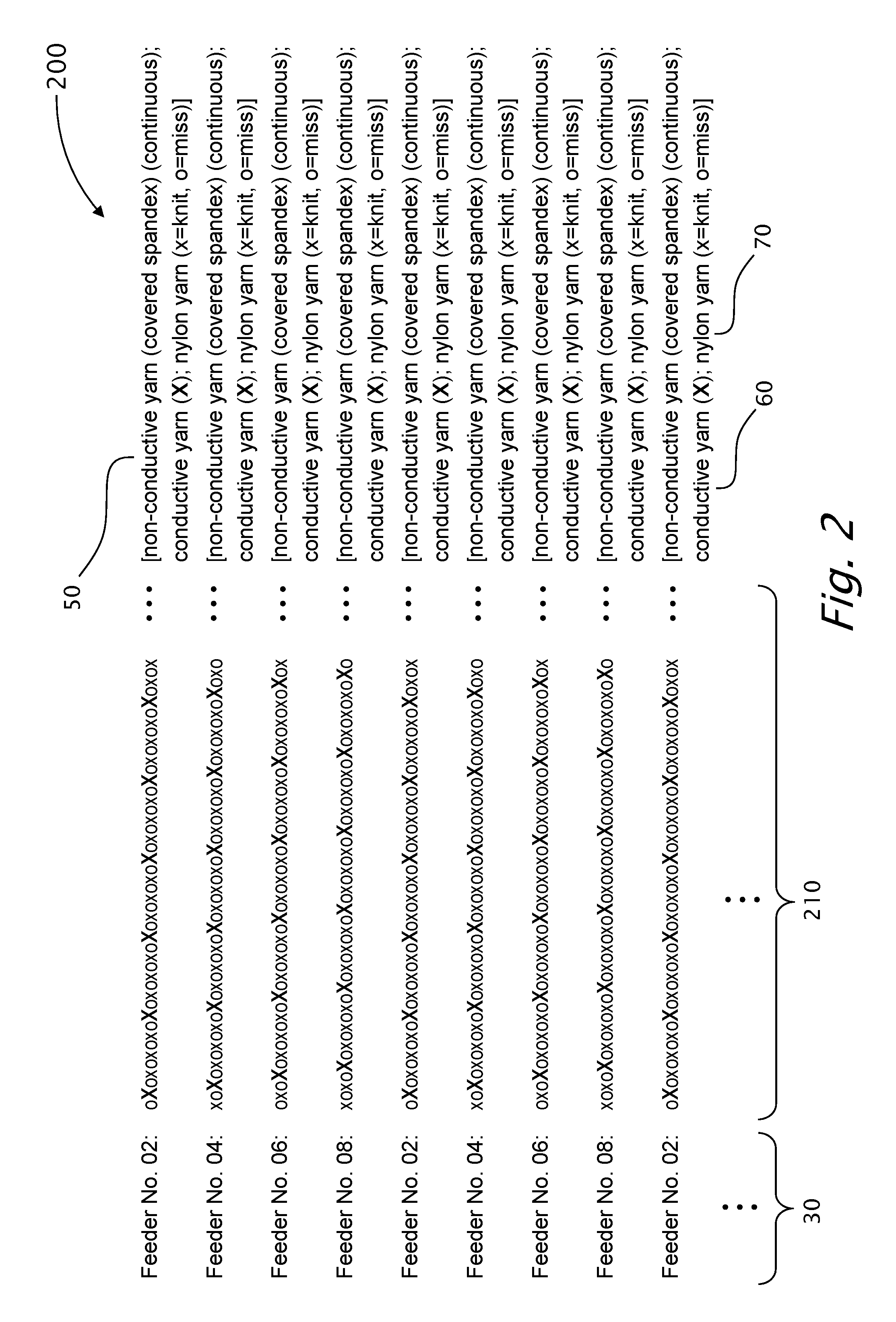

Image

  • Method for limiting elasticity of selected regions in knitted fabrics
  • Method for limiting elasticity of selected regions in knitted fabrics
  • Method for limiting elasticity of selected regions in knitted fabrics

Examples


Embodiment Construction

[0053]The present invention will now be described more fully hereinafter with reference to the accompanying drawings, in which preferred embodiments of the invention are shown. This invention may, however, be embodied in many different forms and should not be construed as limited to the embodiments set forth herein; rather, these embodiments are provided, so that this disclosure will be thorough and complete, and will fully convey the scope of the invention to those skilled in the art.

[0054]An embodiment is an example or implementation of the inventions. The various appearances of “one embodiment,”“an embodiment” or “some embodiments” do not necessarily all refer to the same embodiments. Although various features of the invention may be described in the context of a single embodiment, the features may also be provided separately or in any suitable combination. Conversely, although the invention may be described herein in the context of separate embodiments for clarity, the invention...


PUM

PropertyMeasurementUnit
elasticityaaaaaaaaaa
conductiveaaaaaaaaaa
melting pointaaaaaaaaaa

Abstract

A method for substantially reducing the elasticity of at least one selected textile region of a garment. The method includes producing the garment including a conductive textile electrode and rigidifying the at least one selected textile region. The rigidifying process includes applying rigidifying matter onto or into the at least one selected textile region. The at least one selected textile region is selected from the group consisting of a conductive textile electrode and a region of the garment situated between two adjacent textile electrodes. The invention further provides a garment having a tubular form, knitted by a seamless knitting machine with base-yarns. The garment includes at least one conductive textile electrode, composed of multiple knitted line segments, each knitted with a conductive yarn and a spandex yarn, wherein the spandex yarn and at least one base-yarn are knitted continuously.

Description

CROSS REFERENCE TO RELATED APPLICATIONS[0001]This application is a U.S. national stage entry of an International Application serial no. PCT / IL2014 / 050134 which claims the benefit under 35 USC 119(e) from U.S. provisional application 61 / 763,963 filed Feb. 13, 2013, and from U.S. provisional application 61 / 771,874 filed Mar. 3, 2013, the disclosures of which are included herein by reference.FIELD OF THE INVENTION[0002]The present invention relates to knitted fabrics and more particularly, the present invention relates to wearable health monitoring systems, having knitted electrodes, wherein the knitted electrodes and the knitted fabric in the vicinity of the knitted electrodes are devised to maintain substantially steady dimensions and a substantially steady distance from each other, in particular, between horizontally adjacent electrodes.BACKGROUND OF THE INVENTION AND PRIOR ART[0003]Knitted electrodes in the garment are made of conductive yarn, which conductive yarn is knitted toget...

Claims


Application Information

Patent Timeline
Patent Type & Authority Patents(United States)
IPC IPC(8): D04B1/24B32B27/12B32B5/02D04B1/18G06F1/16A61B5/00D06N7/00A61B5/0408
CPCD04B1/18A61B5/04085A61B5/6805G06F1/16D04B1/24D04B1/246B32B27/12B32B5/026D06N7/0094A41D2400/32D10B2403/02431B32B2535/00B32B2437/00B32B2307/536D06N2209/108A61B2562/125G06F1/163A61B5/282A61B5/318A61B5/0006A61B5/6804
Inventor SHOSHANI, BOAZAMIR, URI
Owner HEALTHWATCH LTD
Learn More