
Multiphase converter controller with current balance

a multi-phase converter and current balance technology, applied in the field of multi-phase converter controllers, can solve the problems of complex circuits, poor transient response, and conventional multi-phase converters, and achieve the effects of improving the transient response of the circuit, poor definition of the current balance, and high cos

Active Publication Date: 2016-08-02
GREEN SOLUTION TECH CO LTD
View PDF18 Cites 3 Cited by
  • Summary
  • Abstract
  • Description
  • Claims
  • Application Information

AI Technical Summary

Benefits of technology

The solution enhances transient response, reduces circuit complexity and cost, and improves current balance, leading to increased reliability and extended component lifespan by using a single timer and feedback-controlled pulse width adjustments.

Problems solved by technology

The conventional multiphase converter circuit has the problems of the poor transient response, the complex circuit, the high cost and the poor definition of the current balance.

Method used


Image

  • Multiphase converter controller with current balance
  • Multiphase converter controller with current balance
  • Multiphase converter controller with current balance

Examples


Embodiment Construction

[0023]In the following detailed description, for purposes of explanation, numerous specific details are set forth in order to provide a thorough understanding of the disclosed embodiments. It will be apparent, however, that one or more embodiments may be practiced without these specific details. In other instances, well-known structures and devices are schematically shown in order to simplify the drawings.

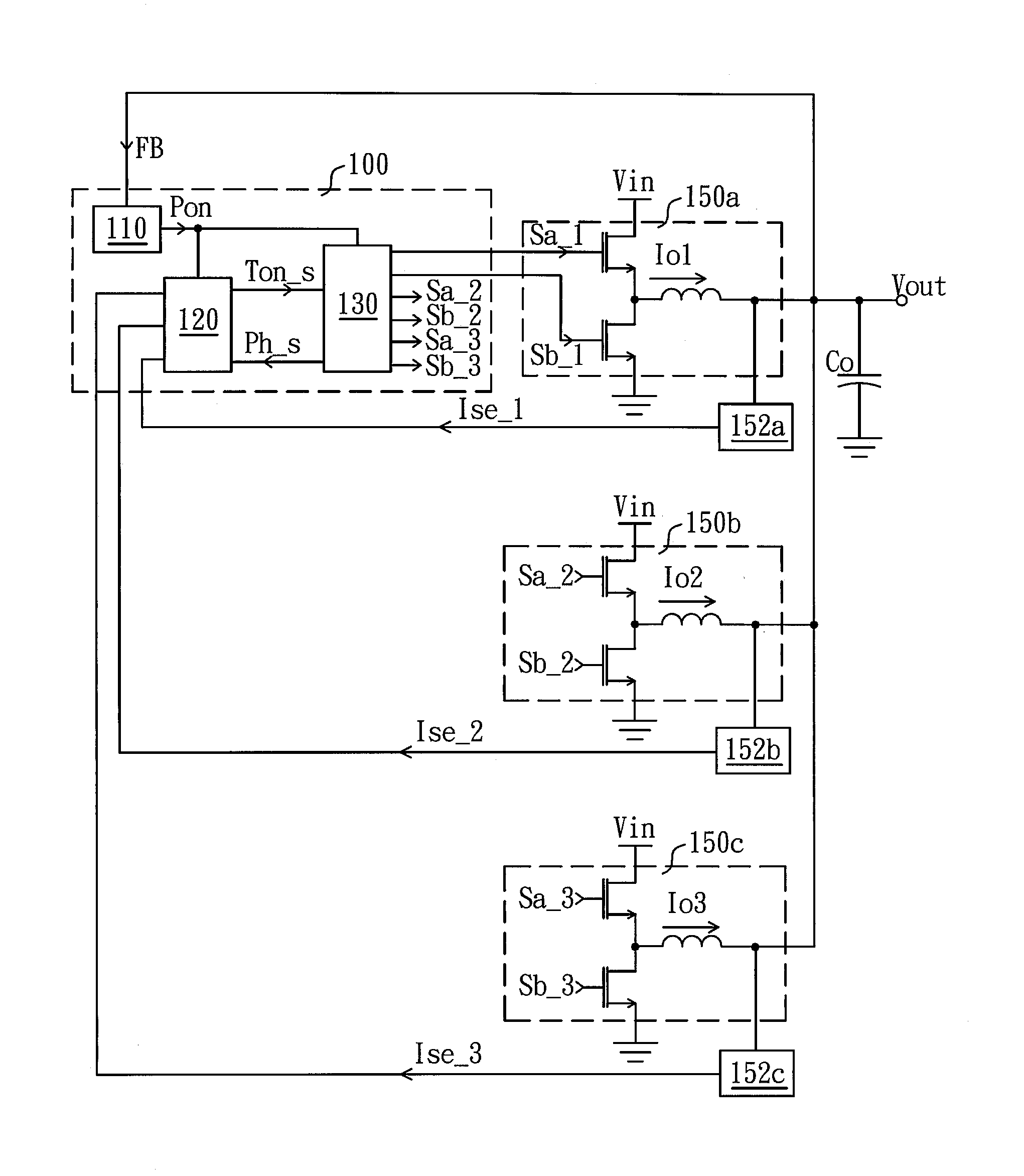
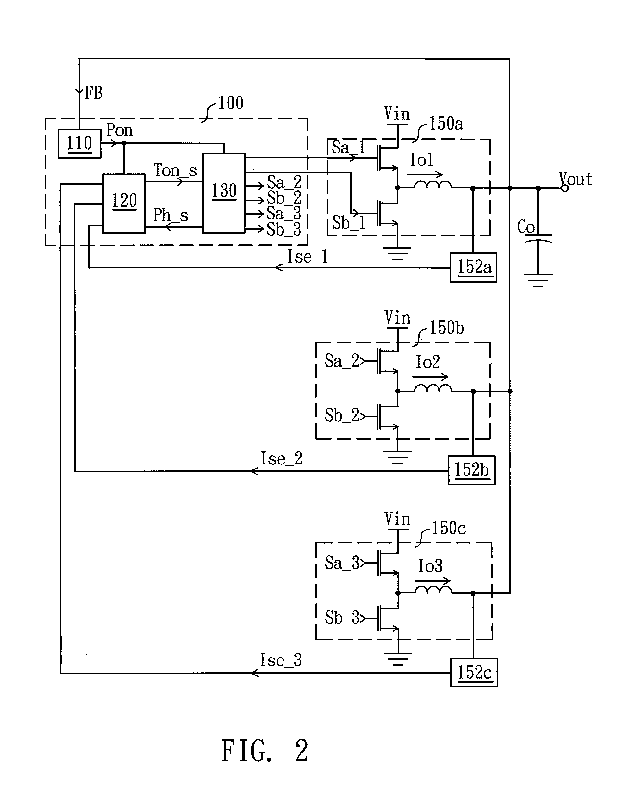
[0024]FIG. 2 is a schematic diagram of a multiphase converter circuit with current balance according to a preferred embodiment of the present invention. The multiphase converter controller 100 controls a plural converting circuit 150a˜150c to commonly supply an output voltage Vout. The converting circuits of the present embodiment are DC-DC buck converter circuits. Each of the DC-DC buck converter circuit comprises an upper side transistor, a lower side transistor and an inductance. The upper side transistor is coupled to an input voltage Vin, and transmits the power from the input...


PUM


Abstract

A multiphase converter controller with current balance, configured to control a plural converting circuit to commonly supply an output voltage, is disclosed. The multiphase converter controller comprises a feedback circuit, a fixed on-time circuit, and a multiphase logical circuit. The feedback circuit detects the output voltage to generate a feedback control signal. The fixed on-time circuit generates an on-time signal according to the feedback control signal, and a pulse width of the on-time signal is determined according to a single timer. The multiphase logical circuit chooses a corresponding converting circuit, generates a phase signal according to a sequence of the feedback control signal and controls the corresponding converting circuit according to the on-time signal. Wherein, the fixed on-time circuit determines a correction value according to currents of the plural converting circuit and the phase signal, so as to correct the pulse width of the on-time signal.

Description

BACKGROUND OF THE INVENTION[0001](1) Field of the Invention[0002]The present relates to a multiphase converter controller, and more particularly relates to a multiphase converter controller with current balance.[0003](2) Description of the Prior Art[0004]With the evolution of the process technology, the integrated circuit becomes gradually miniaturized while the driving voltage being reduced. However the power consumption of the integrated circuits in some field is not reduced with the reduction proportion of driving voltage. It results in that the operating current of the integrated circuit reversely increases.[0005]A power supply for driving the integrated circuit is mainly supplied by a switching power supply. A switch operating of the switching power supply causes a voltage ripple in the supplied voltage. These voltage ripples is more obvious when the driving voltage of the integrated circuits lower, and even causes erroneous operation of the integrated circuit. For decreasing t...

Claims


Application Information

Patent Timeline
Patent Type & Authority Patents(United States)
IPC IPC(8): H02M3/156H02M3/158
CPCH02M3/1584
Inventor LEE, LI-MINGAN, QUANSHIU, SHIAN-SUNGSHAO, CHAO
Owner GREEN SOLUTION TECH CO LTD
Learn More