Heat exchange system configured with a membrane contactor

a technology of contactor and heat exchange system, which is applied in the direction of filtration separation, lighting and heating apparatus, separation processes, etc., can solve the problems of scarce and highly regulated commodity, and reducing the efficiency of evaporative cooler

Active Publication Date: 2016-08-02
RTX CORP
View PDF19 Cites 30 Cited by
  • Summary
  • Abstract
  • Description
  • Claims
  • Application Information

AI Technical Summary

Problems solved by technology

The scale may increase pressure drop across the cooler surface and / or the heat exchanger surface and decrease the efficiency of the evaporative cooler and, thus, the geothermal and / or low grade waste heat driven power system.
Potable water, however, may be a scarce and highly regulated commodity in many regions of the world and, thus, not available for use in a geothermal power system.

Method used


Image

  • Heat exchange system configured with a membrane contactor
  • Heat exchange system configured with a membrane contactor
  • Heat exchange system configured with a membrane contactor

Examples


Embodiment Construction

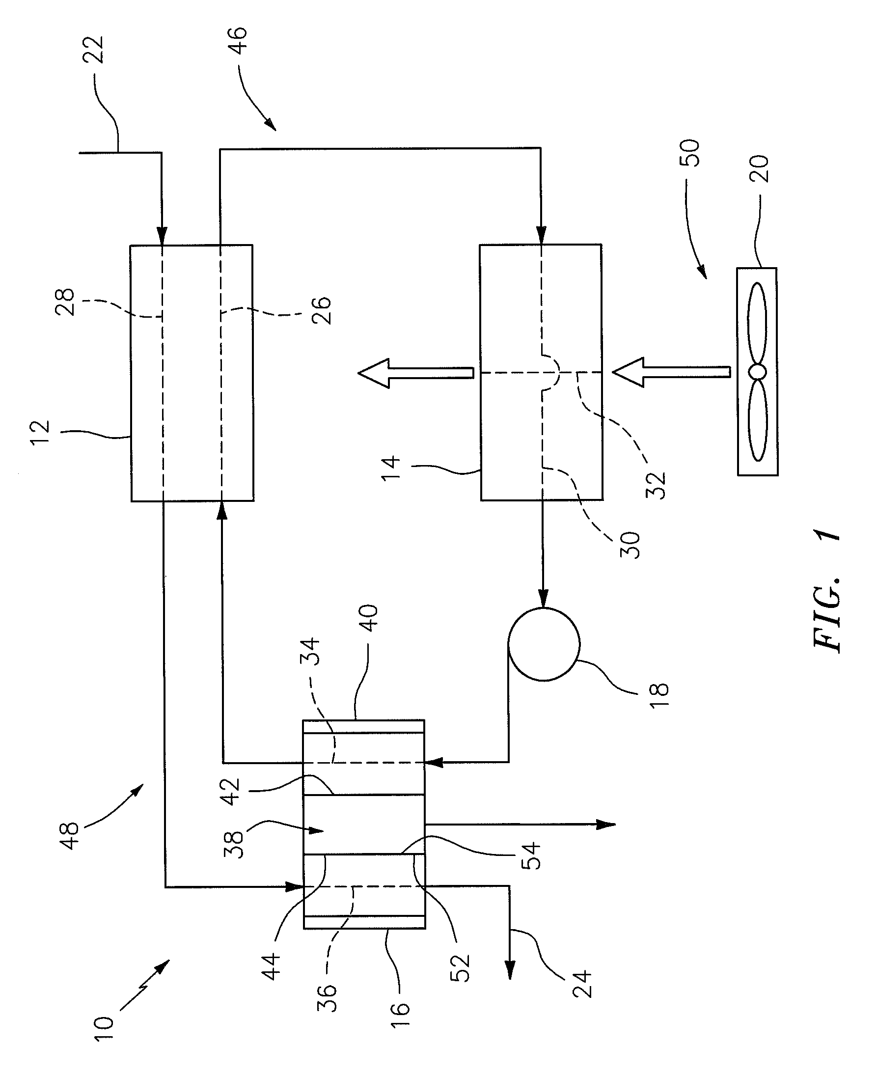
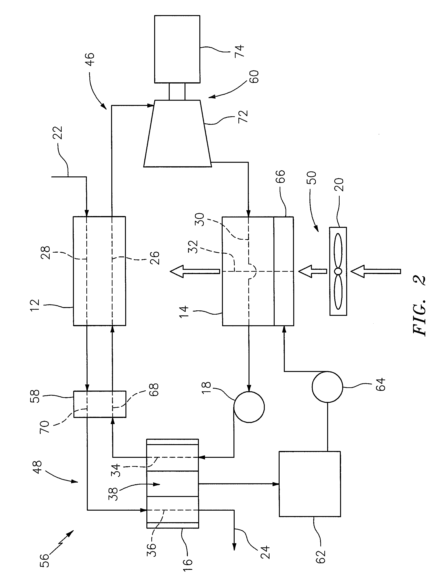
[0013]FIG. 1 illustrates a heat exchange system 10 that may be configured as, for example, a geothermal heating system. The system 10 includes a first heat exchanger 12, a second heat exchanger 14 and a membrane contactor 16. The system 10 may also include a first flow regulator 18 (e.g., a pump, a compressor and / or a valve), a second flow regulator 20 (e.g., a fan, a blower, a vacuum and / or a pump), a working fluid inlet 22 and / or a working fluid outlet 24.

[0014]The first heat exchanger 12 may be configured as a (e.g., counter-flow) liquid-to-liquid evaporator. The first heat exchanger 12 includes a first heat exchange passage 26 and a second heat exchange passage 28.

[0015]The second heat exchanger 14 may be configured as a liquid-to-gas condenser. The second heat exchanger 14 includes a first heat exchange passage 30 and a second heat exchange passage 32 (e.g., an airflow duct).

[0016]The membrane contactor 16 may be configured as a liquid gap membrane distillation device, an air g...


PUM

PropertyMeasurementUnit
heat energyaaaaaaaaaa
temperatureaaaaaaaaaa
electrical poweraaaaaaaaaa

Abstract

A heat exchange system may include a first heat exchange circuit and a second heat exchange circuit. The first heat exchange circuit may circulate a first working fluid sequentially through a first heat exchanger, a second heat exchanger and a membrane contactor. The second heat exchange circuit may direct a second working fluid sequentially through the first heat exchanger and the membrane contactor, where the second working fluid includes solute and solvent. The first heat exchanger and the membrane contactor may transfer heat energy from the second working fluid to the first working fluid, and the second heat exchanger may transfer heat energy from the first working fluid to a third working fluid. The membrane contactor may extract a portion of the solvent from the second working fluid.

Description

BACKGROUND OF THE INVENTION[0001]1. Technical Field[0002]The present invention relates generally to a heat exchange system and, in particular, to a heat exchange system that may, for example, provide cooling to an electrical power generation system and produce distilled water utilizing geothermal energy and / or low grade waste heat.[0003]2. Background Information[0004]A cooling system for a geothermal and / or a low grade waste heat driven power system may include a pre-cooler such as an evaporative cooler or mister that pre-cools ambient air provided to a condenser. A typical evaporative cooler may include an evaporative cooler surface housed within a cooler duct. During operation, water is directed through the cooler surface, and air is directed through the cooler duct. The water may evaporate into the air as the air passes through the cooler surface. Heat energy from the air may be absorbed by heat of vaporization of the evaporating water, thereby cooling the air. The cooling system...

Claims


Application Information

Patent Timeline
Patent Type & Authority Patents(United States)
IPC IPC(8): B01D35/10F28C3/08F24J3/08C02F1/16B01D3/00C02F1/02C02F1/44B01D63/00B01D35/18F28D21/00F28D15/02
CPCB01D3/007C02F1/16F24J3/08F28C3/08F28D21/0015F28D21/0001Y02W10/37F28D15/0266Y02E10/10F24T10/30
Inventor WU, HAILINGMA, ZIDU
Owner RTX CORP
Why Eureka
Try Eureka