
Orthopedic systems for spine and tracking control

a tracking control and orthopedic technology, applied in the field of orthopedic systems for spine treatment, can solve the problems of not giving a large amount of flexibility in the operating room for the end user, not allowing bone ingrowth, and high incidence of implant subsidence into the vertebral body, so as to prevent the rotation of the mating mechanism

Active Publication Date: 2016-07-12
TYBER MEDICAL
View PDF20 Cites 74 Cited by
  • Summary
  • Abstract
  • Description
  • Claims
  • Application Information

AI Technical Summary

Benefits of technology

The solution effectively reduces subsidence and enhances bone growth by distributing loads through bone graft material, increasing the fusion area and minimizing the risk of pseudo-arthrosis while maintaining low stiffness for better compatibility with vertebral endplates.

Problems solved by technology

However, in intervertebral spacers, titanium is not the preferred choice due to its high stiffness compared with bone.
The large stiffness differential between bone and titanium has caused a high incidence of subsidence of the implant into the vertebral body.
However, PEEK is not an osteoconductive material and a large central oval cavity is the only space designed for bone through growth, thus the spacers remove a larger percentage of the fusion area.
These systems typically utilize specifically designed plates to interbody connections and do not give a large amount of flexibility in the operating room for the end user to interoperatively switch between a standalone interbody and an isolated interbody.
In addition, the interbodies used in the standalone assemblies are constructed of the same inert material and do not allow for bone ingrowth to occur.
The lack of fusion area increases the strength of the fixation required to maintain the construct rigidity during healing.
This includes small devices that lack sufficient surface area to contain a distinguishable UDI.

Method used


Image

  • Orthopedic systems for spine and tracking control
  • Orthopedic systems for spine and tracking control
  • Orthopedic systems for spine and tracking control

Examples


Embodiment Construction

[0055]In the drawings, like numerals indicate like elements throughout. Certain terminology is used herein for convenience only and is not to be taken as a limitation on the present invention. For purposes of this description, the terms “anterior”, “posterior”, “superior” and “inferior” describe the position of surfaces or features relative to the anatomy. The term “anterior” refers to features having a relative position toward the front side of a spine, and “posterior” refers to features having a relative position toward the rear side of the spine. The term “superior” refers to features having a relative position above other features, in the cranial direction, and the term “inferior” refers to features having a relative position below other features in a caudal direction. The terminology includes the words specifically mentioned, derivatives thereof and words of similar import.

[0056]The embodiments illustrated below are not intended to be exhaustive or to limit the invention to the...


PUM

PropertyMeasurementUnit
Young's modulusaaaaaaaaaa
crest angleaaaaaaaaaa

Abstract

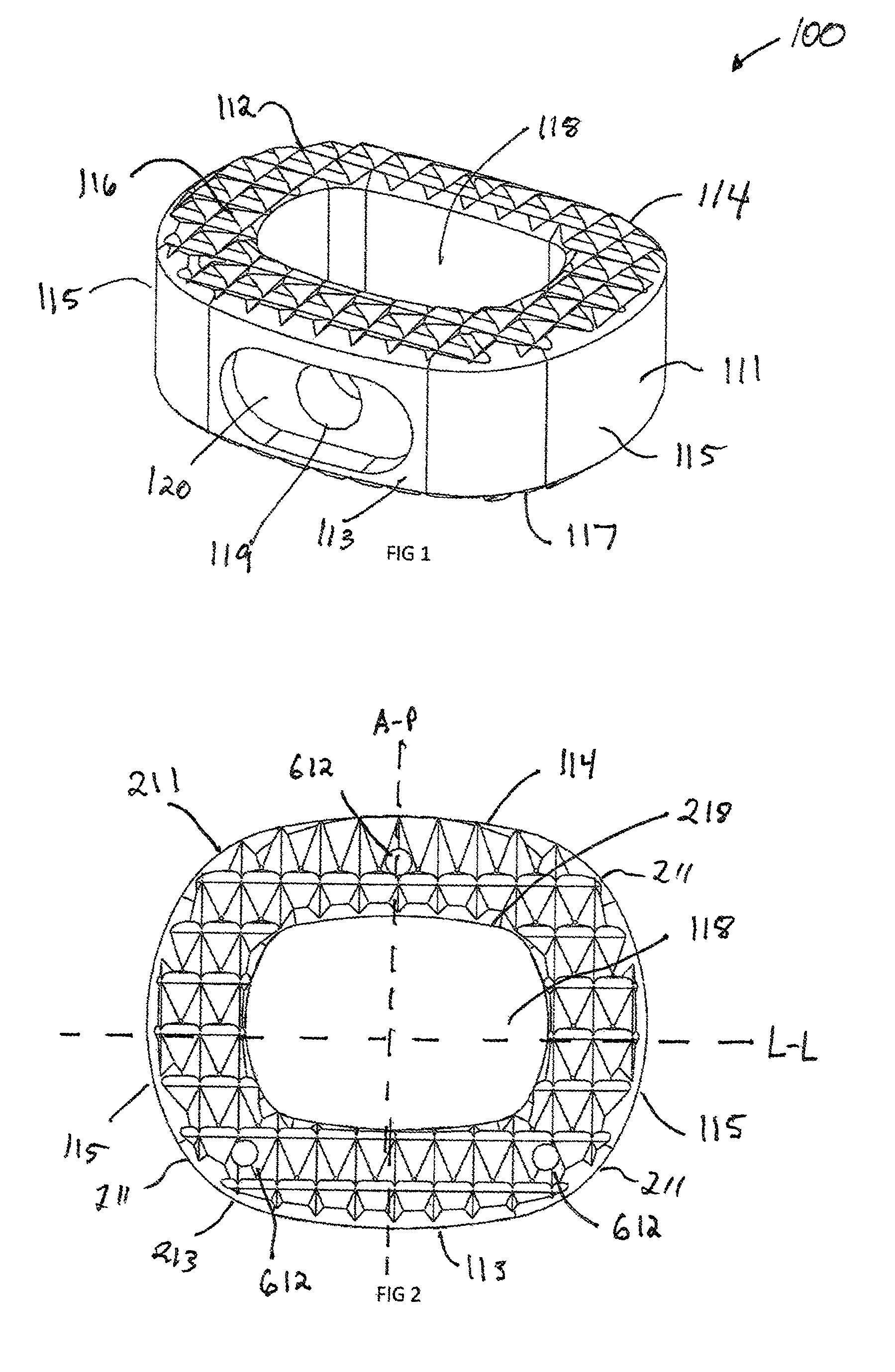
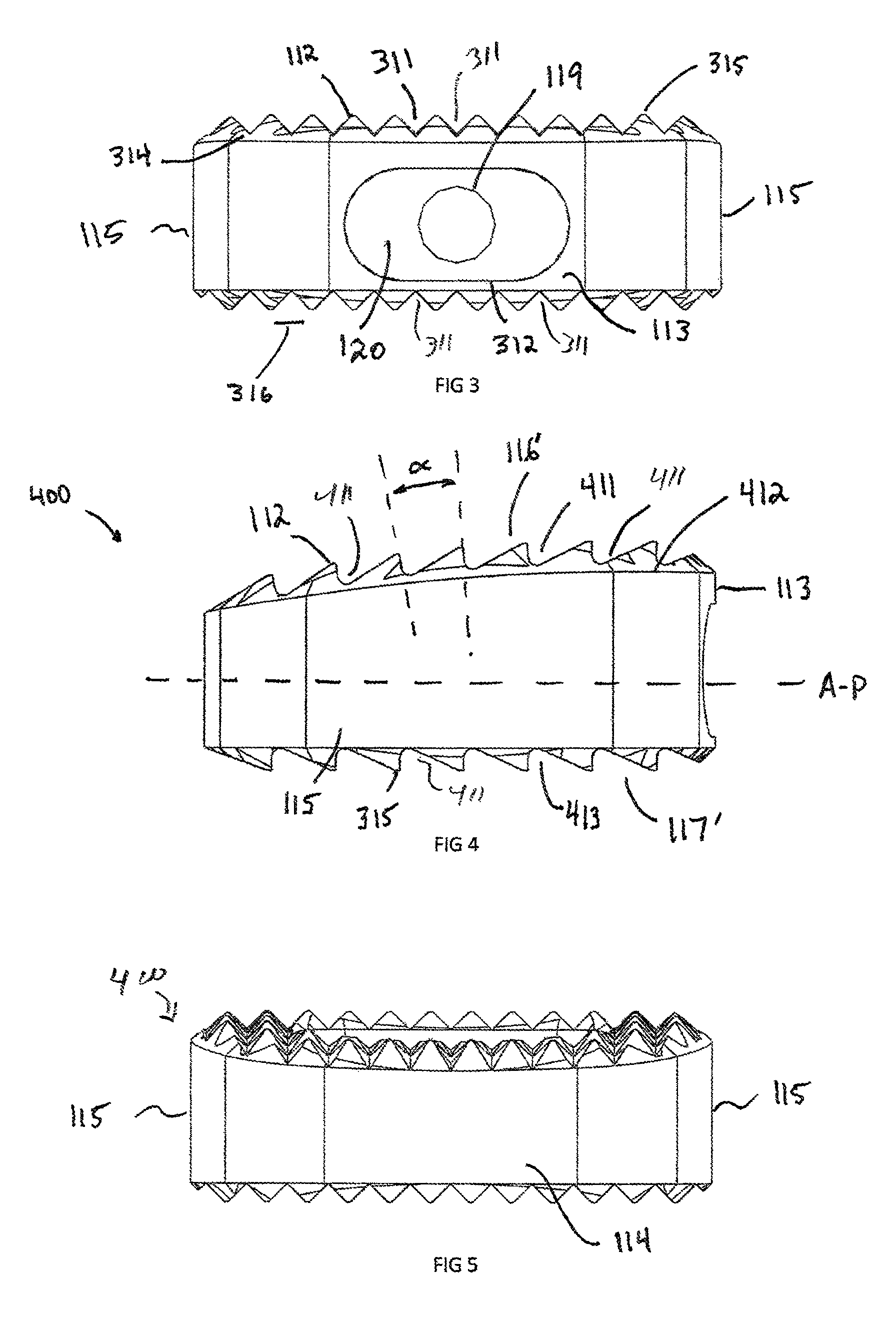
An orthopedic implant system includes an intervertebral implant. The implant includes a body having an upper surface extending generally in a first plane. The upper surface has a first plurality of longitudinal grooves and a second plurality of transverse grooves extending therealong. Portions of the upper surface extend between adjacent longitudinal grooves and transverse grooves form individual peaks. A lower surface extends generally in a second plane, parallel to the first plane. The lower surface has a third plurality of longitudinal grooves and a fourth plurality of transverse grooves extending therealong. Portions of the lower surface extend between adjacent longitudinal grooves and transverse grooves form individual peaks.

Description

CROSS-REFERENCE TO RELATED APPLICATIONS[0001]The present application claims priority from U.S. Provisional Patent Application Ser. No. 61 / 715,891, filed on Oct. 19, 2012, which is incorporated by reference herein in its entirety.FIELD OF THE INVENTION[0002]The present invention generally relates to an orthopedic systems for treatment of the spine specifically intervertebral implants, containing mechanism to rigidly attach to the vertebrae and systems for full lot control traceability.BACKGROUND OF THE INVENTION[0003]Anterior intervertebral interbody fusion is a common technique for treating degenerative disc disease and major deformity. The anterior approach is common for both the cervical (ACIF) and lumbar (ALIF) spine. The approach allows full visibility of the disc and fusion site, while minimizing disruptions to the branch nerves of the spinal column as well as major trauma to the posterior musculature. Typical intervertebral fusion consists of an interbody spacer and a fixation...

Claims


Application Information

Patent Timeline
Patent Type & Authority Patents(United States)
IPC IPC(8): A61F2/44A61B17/86A61F2/46A61B17/70A61B17/80A61F2/30
CPCA61B17/863A61B17/865A61F2/447A61F2/4465A61F2/4455A61B17/7059A61B17/8052A61B17/8095A61F2/4611A61B17/8645A61F2/30771A61F2002/3008A61F2002/30013A61F2002/3082A61F2002/3092A61F2002/3093A61F2002/30281A61F2002/30355A61F2002/30509A61F2002/30578A61F2002/30714A61F2002/30774A61F2002/30808A61F2002/30836A61F2002/30843A61F2002/4475A61F2002/4623A61F2002/4627A61F2310/00407A61F2310/00461A61F2310/00796A61F2/4603A61F2002/30011A61F2002/30507A61F2002/30593A61F2002/3071A61B90/94
Inventor TYBER, JEFFREY
Owner TYBER MEDICAL
Learn More