
Method and system for dynamically calibrating vehicular cameras

a dynamic calibration and camera technology, applied in the field of methods, can solve problems such as visible visual distortion in the composite 360 degree image, the end of line testing method does not solve the problem, and the inability to use end-of-line assembly line calibration based on predetermined targets in a controlled environment,

Active Publication Date: 2016-05-31
MAGNA ELECTRONICS INC
View PDF295 Cites 36 Cited by
  • Summary
  • Abstract
  • Description
  • Claims
  • Application Information

AI Technical Summary

Benefits of technology

Enables accurate and automatic calibration of vehicular cameras in the field, ensuring seamless composite 360-degree images and enhancing driver assistance systems like object detection and lane departure warning by accounting for rotational changes.

Problems solved by technology

A problem arises in attempting to stitch together the aforesaid camera images into a single composite image in that each camera is not absolutely fixed in position.
However, this end of line testing method does not solve the problem of being able to independently calibrate the cameras in the field, where there is no controlled environment in which pre-designated markers are situated at known locations.
Simply put, it is not possible to use end-of-line assembly line calibration based on predetermined targets in a controlled environment to calibrate a vehicular camera in the field.
In attempting to stitch together the images from the four cameras based on predetermined demarcation lines defined with respect to nominally positioned cameras, it was noticed that changes in the three rotational degrees of freedom in particular result in a noticeable visual distortion in the composite 360 degrees image.

Method used


Image

  • Method and system for dynamically calibrating vehicular cameras
  • Method and system for dynamically calibrating vehicular cameras
  • Method and system for dynamically calibrating vehicular cameras

Examples


Embodiment Construction

[0044]In this document, unless the context dictates otherwise, the following terms have the following meanings:

[0045]“ground plane” refers to a real plane parallel to the roadway.

[0046]“image plane” refers to a two-dimensional space provided as an output of a camera viewing a real three-dimensional space.

[0047]“plane at infinity” means all points at infinity, and refers to a plane that is perpendicular to the ground plane.

[0048]“horizon line” is the intersection of the ground plane with the plane at infinity.

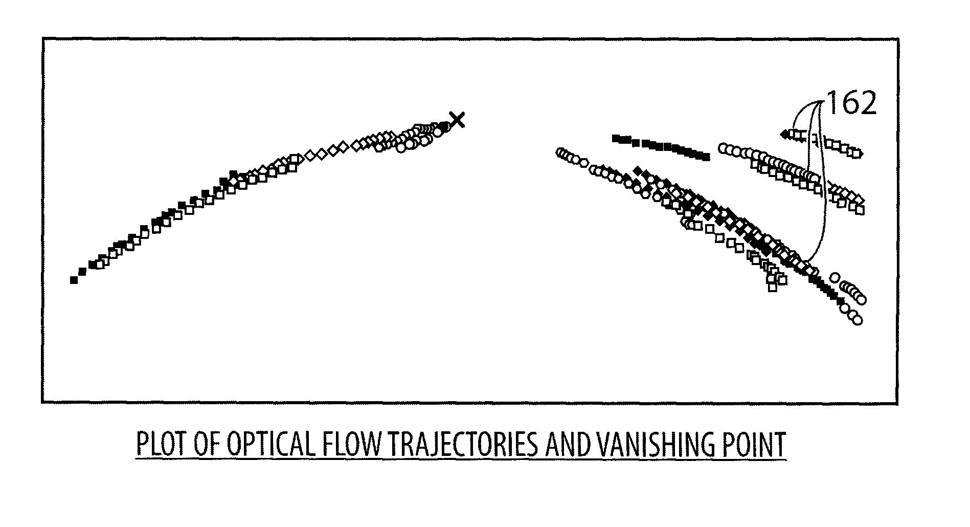
[0049]“vanishing point” is a point at which parallel lines in the ground plane seem to converge in an image plane. If the camera is centered between two parallel lines in the ground plane which are parallel to the camera optical axis, the intersection of the two parallel lines is referred to as the “central vanishing point”.

[0050]“principal point” refers to the central vanishing point of a camera when the camera is at its nominal installed position and orientation. This principa...


PUM


Abstract

A method of dynamically ascertaining the alignment of a vehicular camera. The method involves acquiring a sequence of images provided by the camera whilst the vehicle is in motion. For each range of steering angles, the method (i) selects a plurality of feature points in the images, (ii) tracks a motion trajectory for each selected feature point, and (iii) determines a vanishing point in the image plane based on the tracked motion trajectories. The method determines a vanishing line in the image plane based on a locus of these vanishing points and determines the alignment of the camera based on the position of a central vanishing point (corresponding to the zero degree angle) and the vanishing line.

Description

CROSS REFERENCE TO RELATED APPLICATIONS[0001]The present application is a 371 national phase application of PCT appliication No. PCT / CA2012 / 000056, filed Jan. 20, 2012, which claims priority to U.S. Provisional Application Ser. No. 61 / 478,711, filed Apr. 25, 2011, the contents of which are incorporated by reference herein in their entirety.FIELD OF INVENTION[0002]The invention relates to the field of vehicular cameras, and more particularly to methods and systems for dynamically calibrating the position or alignment of a vehicular camera in the field.BACKGROUND OF INVENTION[0003]In an effort to provide drivers with a comprehensive view of their surroundings, vehicle manufacturers have recently proposed and marketed 360 degree vision systems which display a “bird's eye” view of the vehicle and its surroundings. Such 360 degree vision systems typically utilize four wide angle cameras, one at the front of the vehicle, one at the rear and two at the sides. The outputs of these four came...

Claims


Application Information

Patent Timeline
Patent Type & Authority Patents(United States)
IPC IPC(8): H04N7/18H04N17/00G06T7/00H04N23/90
CPCH04N17/00G06T7/0018B60R2300/105B60R2300/8086B60R2300/8093G06T2207/30252G06T7/80B60R2300/402H04N17/002
Inventor GUPTA, NIKHILFARAJI, HILDAHE, DAANRATHI, GHANSHYAM
Owner MAGNA ELECTRONICS INC
Learn More